MONSTER - A learning experience... pyVCP machine

18 Nov 2014 14:40 - 20 Nov 2014 04:13 #53186
by Askjerry
MONSTER - A learning experience... pyVCP machine was created by Askjerry
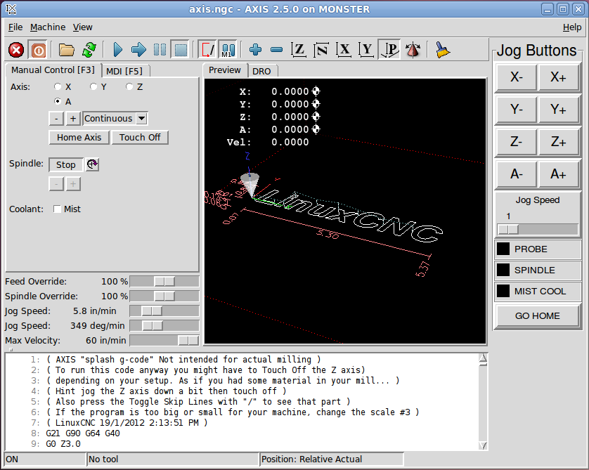
pyVCP Example
I had set up my machine a couple of months ago... 3-axis Wells Index 847 machine, then added a 4th axis to that. I wanted some more functionality so I figured out how to add JOG buttons for the different axis. I got all excited and decided to install Glade, and make a killer interface. After three days... I decided to go back to the pyVCP to see if it would do what I wanted...
1) JOG and other control buttons.
2) Easy to read display for mist and spindle running.
3) Indicator to tell if the probe was detecting or not.
4) Ability to call subroutines and/or canned files to do complex "stuff".
After only one day of beating my head against the computer... I figured out how to accomplish ALL the tasks above. I'm going to add even more functionality and clean up the console a bit... but I'm proud of what I have, and I wanted to put it out there for anyone else who may be having issues. You can load it on your machine and tinker as much as you like... my gift to the community. I have a big mill... so I called the setup MONSTER.
My machine logon is "askjerry" so you will need to change that to whatever YOUR logon is in the path specification.
in the file monster.ini file, you need to findThen change the "askjerry" to whatever your machine is called.
When you want to add new G-Code (MDI) routines to this setup... and you can do 63 more... put them under the [HALUI] section... you will see my first one...This calls the "go_home.ngc" file I have in the ROUTINES folder.
Things I learned...
It takes (4) four files to pull this all together...
-- MONSTER.ini
-- custompanel.xml
-- custom_postgui.hal
-- G-Code file(s) in the ROUTINES folder.
MONSTER.ini
Under the [DISPLAY] heading you must specify the name of the xml file that describes how to build all your buttons, LEDs, etc
In my case this line reads...You must also specify the SUBROUTINE_PATH so it knows where to find your custom G-Code, we covered that above.
Also covered above... the [HALUI] section specifies the names of your G-Code file(s).
custompanel.xml
This is where your XML code to build the layout is created. Read the INTEGRATOR MANUAL... it covers this fairly well.
custom_postgui.hal
This file is what connects the panel "stuff" to the actual hardware. You will see lines that look like...Let me break that line of code down for you...
panel-jogxminus is a variable or pointer name that you create for the machine to reference... since it had to do with my panel... I named it with that for a start.
halui.jog.0.minus is a LinuxCNC reference signal... from the AXIS display, click the MACHINE tab, then "HAL CONFIGURATION"... it lists all the pins, signals, and things of that nature... took me two days to figure that out.
<= This is optional... and tells us that the panel is going to send signals to the machine... for the LED... it looks like => because the machine is sending the signal to the panel.
pyvcp.x-minus This is a combination of pyvcp (the name of the panel) and the variable/pointer inside the panel... in this case my x-minus button.
G-Code
Last but definitely not least... I created a folder called ROUTINES where I can put any G-Code files that I want to run.
For the one button I have now... I want to run a file called go_home.ngc so this is specified asin the MONSTER.ini file.
This file is actually pretty simple... move Z up an inch, then go to X/Y/A zero points, then drop the Z down to zero as well. Everybody ends up home.
I know this post is pretty long... but I wanted everything in one place so people could find it.
The ZIP file below is everything you need... unzip the files, and copy them into your configs folder... then have fun.
I hope you find this information helpful.
Jerry
(Later I hope to have some tutorial videos online.)
I had set up my machine a couple of months ago... 3-axis Wells Index 847 machine, then added a 4th axis to that. I wanted some more functionality so I figured out how to add JOG buttons for the different axis. I got all excited and decided to install Glade, and make a killer interface. After three days... I decided to go back to the pyVCP to see if it would do what I wanted...
1) JOG and other control buttons.
2) Easy to read display for mist and spindle running.
3) Indicator to tell if the probe was detecting or not.
4) Ability to call subroutines and/or canned files to do complex "stuff".
After only one day of beating my head against the computer... I figured out how to accomplish ALL the tasks above. I'm going to add even more functionality and clean up the console a bit... but I'm proud of what I have, and I wanted to put it out there for anyone else who may be having issues. You can load it on your machine and tinker as much as you like... my gift to the community. I have a big mill... so I called the setup MONSTER.
My machine logon is "askjerry" so you will need to change that to whatever YOUR logon is in the path specification.
in the file monster.ini file, you need to find
[RS274NGC]
PARAMETER_FILE = linuxcnc.var
SUBROUTINE_PATH = /home/askjerry/linuxcnc/configs/MONSTER/ROUTINES/When you want to add new G-Code (MDI) routines to this setup... and you can do 63 more... put them under the [HALUI] section... you will see my first one...
MDI_COMMAND = O <go_home> CALLThings I learned...
It takes (4) four files to pull this all together...
-- MONSTER.ini
-- custompanel.xml
-- custom_postgui.hal
-- G-Code file(s) in the ROUTINES folder.
MONSTER.ini
Under the [DISPLAY] heading you must specify the name of the xml file that describes how to build all your buttons, LEDs, etc
In my case this line reads...
PYVCP = custompanel.xmlAlso covered above... the [HALUI] section specifies the names of your G-Code file(s).
custompanel.xml
This is where your XML code to build the layout is created. Read the INTEGRATOR MANUAL... it covers this fairly well.
custom_postgui.hal
This file is what connects the panel "stuff" to the actual hardware. You will see lines that look like...
net panel-jogxminus halui.jog.0.minus <= pyvcp.x-minuspanel-jogxminus is a variable or pointer name that you create for the machine to reference... since it had to do with my panel... I named it with that for a start.
halui.jog.0.minus is a LinuxCNC reference signal... from the AXIS display, click the MACHINE tab, then "HAL CONFIGURATION"... it lists all the pins, signals, and things of that nature... took me two days to figure that out.
<= This is optional... and tells us that the panel is going to send signals to the machine... for the LED... it looks like => because the machine is sending the signal to the panel.
pyvcp.x-minus This is a combination of pyvcp (the name of the panel) and the variable/pointer inside the panel... in this case my x-minus button.
G-Code
Last but definitely not least... I created a folder called ROUTINES where I can put any G-Code files that I want to run.
For the one button I have now... I want to run a file called go_home.ngc so this is specified as
[HALUI]
# add halui MDI commands here (max 64)
MDI_COMMAND = O <go_home> CALLThis file is actually pretty simple... move Z up an inch, then go to X/Y/A zero points, then drop the Z down to zero as well. Everybody ends up home.
(go_home.ngc)
(CMD-00 Go to HOME position)
O <go_home> sub
G00 Z1
G00 X0 Y0 A0
G00 Z0
O <go_home> endsub
M2
I know this post is pretty long... but I wanted everything in one place so people could find it.
The ZIP file below is everything you need... unzip the files, and copy them into your configs folder... then have fun.
I hope you find this information helpful.
Jerry
(Later I hope to have some tutorial videos online.)
Last edit: 20 Nov 2014 04:13 by Askjerry.
The following user(s) said Thank You: Cheech
Please Log in or Create an account to join the conversation.
19 Nov 2014 04:16 - 20 Nov 2014 04:14 #53197
by Askjerry
Replied by Askjerry on topic MONSTER - A learning experience... pyVCP machine
The Probe
So the panel is moving along nicely... now to get the probe functional... after all, that was the plan from the beginning. The probe is connected to PIN-15 in the stepconfig, so I was able to get it to register as a panel LED just fine. I thought it was all good... but if I issue a G38.2 or a G38.3 command... the "machine" keeps going until it stops at the commanded point... the probe never registers contact. (even though the LED changes states just fine.)
Let me just show you...
Looking up information on the G-Codes HERE , I get some more information...
You will not be able to use a probe move until your machine has been set up to provide a probe input signal. The probe input signal must be connected to motion.probe-input in a .hal file. G38.x uses motion.probe-input to determine when the probe has made (or lost) contact. TRUE for probe contact closed (touching), FALSE for probe contact open.
Okay... so it mentions the motion.probe-input signal... but here is what I have in my custom_postgui.hal file...
Okay... so here is what we need to do... I wanted the probe to register a contact when it hits a ground... which the system regards as an inverted signal. The trick is to add another line to the custom_postgui.hal file and make that definition.")
Tada!
It's alive!!!
So the panel is moving along nicely... now to get the probe functional... after all, that was the plan from the beginning. The probe is connected to PIN-15 in the stepconfig, so I was able to get it to register as a panel LED just fine. I thought it was all good... but if I issue a G38.2 or a G38.3 command... the "machine" keeps going until it stops at the commanded point... the probe never registers contact. (even though the LED changes states just fine.)
Let me just show you...
Looking up information on the G-Codes HERE , I get some more information...
You will not be able to use a probe move until your machine has been set up to provide a probe input signal. The probe input signal must be connected to motion.probe-input in a .hal file. G38.x uses motion.probe-input to determine when the probe has made (or lost) contact. TRUE for probe contact closed (touching), FALSE for probe contact open.
Okay... so it mentions the motion.probe-input signal... but here is what I have in my custom_postgui.hal file...
# connect the PyCVP probe LED to the parallel port
net panel-probe parport.0.pin-15-in => pyvcp.probe-led
Okay... so here is what we need to do... I wanted the probe to register a contact when it hits a ground... which the system regards as an inverted signal. The trick is to add another line to the custom_postgui.hal file and make that definition.
# connect the PyCVP probe LED to the parallel port
net panel-probe parport.0.pin-15-in => pyvcp.probe-led
# connect the REAL probe to the parallel port inverted pin.
net real-probe parport.0.pin-15-in-not => motion.probe-input
Tada!
It's alive!!!
Last edit: 20 Nov 2014 04:14 by Askjerry. Reason: Remove old ZIP file
Please Log in or Create an account to join the conversation.
20 Nov 2014 04:12 #53221
by Askjerry
Replied by Askjerry on topic MONSTER - A learning experience... pyVCP machine
UPDATE: Now on Version V5
I have really been working at it now... I replaced the PROBE LED with two graphics images... so now you can tell exactly what the probe is doing.
I have the image sideways... but only because I didn't want to give up more vertical space. Here is what it looks like today.
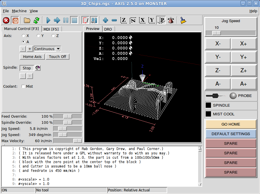
MONSTER V5
I do have a question if someone can answer it...
I would like to make a button that when I press it, the following occurs...
The X and Y axis are UNHOMED
The X and Y axis are HOMED at the current location.
The OFFSETS for X and Y are set to 0.0 inches.
In other words... one click and the machine realized that "HERE" is the correct location for X and Y.
(I'll use the probe later to set the Z-axis once I see how this step is accomplished.)
Thanks!
Jerry
I'm attaching a ZIP with this version for you to play with.
I have really been working at it now... I replaced the PROBE LED with two graphics images... so now you can tell exactly what the probe is doing.
I have the image sideways... but only because I didn't want to give up more vertical space. Here is what it looks like today.
MONSTER V5
I do have a question if someone can answer it...
I would like to make a button that when I press it, the following occurs...
The X and Y axis are UNHOMED
The X and Y axis are HOMED at the current location.
The OFFSETS for X and Y are set to 0.0 inches.
In other words... one click and the machine realized that "HERE" is the correct location for X and Y.
(I'll use the probe later to set the Z-axis once I see how this step is accomplished.)
Thanks!
Jerry
I'm attaching a ZIP with this version for you to play with.
Please Log in or Create an account to join the conversation.
20 Nov 2014 19:42 - 20 Nov 2014 19:46 #53234
by cncbasher
Replied by cncbasher on topic MONSTER - A learning experience... pyVCP machine
Jerry ,
why do you want to move HOME ? this is a once per machine startup session item , i.e when first switched on
this sets the machine internal values and really should not be touched . this is set by your home switches etc and sets other variables
which dont want to be changed .
is what you mean Touch off ( see axis )
People do get confused between homing and touch off , they are not the same thing .
homing is a machine setting , touch off is a user setting , they can of course be the same point in space , which is why it confuses .
touch off :
this is setting the working envelope and interactively moving point zero inside your working area , and can be changed job by job etc
resetting your dro to zero at any point on the table can be done , this is called work coordinates and G54 covers this , you can also to take this a step further
have 6 seperate defined preset points G54 to G59 over your table area .
but to set a button and set touchoff to zero at these points on the fly as it where issue a mdi command
so set up a mdi_command = G10 L20 P0 X0 Y0 Z0
p.s great work so far , your learning ! , nice to document for others going through the learning curve
Dave
Last edit: 20 Nov 2014 19:46 by cncbasher.
Please Log in or Create an account to join the conversation.
20 Nov 2014 22:07 - 20 Nov 2014 22:10 #53240
by Askjerry
Replied by Askjerry on topic MONSTER - A learning experience... pyVCP machine
The machine (at least for the moment) does not have any limit or homing switches. Every time I turn it on, I have to move it to where I want home to be, then manually click X-Home, Y-Home, Z-Home, and A-Home. If you will notice... there is a button programmed to "Set Defaults."
Currently that button has this code assigned...
I just thought it might be nice (until I install hard limit switches) to have a single button I could click at startup.
(I'm a lazy guy cncbasher )
)
Currently that button has this code assigned...
(cmd-01.ngc  Set default machine settings)

O <cmd-01> sub
G17    (Machine to XY Plane)
G20    (Inch Mode)
G40    (Cutter Compensation OFF)
G90    (Absolute Movement Mode)
G94    (Speed in Inches per minute)
G54    (Use Coordinate system P1 G54 Default)
G49    (Cancel any tool length compensation)
G91.1  (Arcs set to default units and method)
M5       (Stop Spindle)
M9       (Stop Coolant)
M48      (Allow Speed Override)

G10 L20 P1 X0 Y0 Z0 A0 (Set current location to ZERO)
O <cmd-01> endsub

M2
I just thought it might be nice (until I install hard limit switches) to have a single button I could click at startup.
(I'm a lazy guy cncbasher
)
Last edit: 20 Nov 2014 22:10 by Askjerry. Reason: Make neater
Please Log in or Create an account to join the conversation.
20 Nov 2014 23:04 #53242
by cncbasher
Replied by cncbasher on topic MONSTER - A learning experience... pyVCP machine
haha an accident waiting to happen kinda guy
BTW grab a copy of the CNC Programming Handbook by Peter Smid
BTW grab a copy of the CNC Programming Handbook by Peter Smid
Please Log in or Create an account to join the conversation.
21 Nov 2014 18:12 #53259
by Askjerry
Replied by Askjerry on topic MONSTER - A learning experience... pyVCP machine
The PROBE
- Bouncing is bad.
I started to use the probe... which for now is a piece of wire sticking down... hey, it's just for testing.
I have a switch on the desk in my office to test my routine... and it works great. But then I take the same code and put it on the big machine in the garage... and it is not too happy. I start getting an error something like "Probe tripped during a non-MDI command" Or basically... it is getting a noisy signal and counting multiple hits instead of a single contact. The fix is to tell it after the initial reading... ignore it for a period of time. That's called DEBOUNCE.
I pulled up the HAL Manual, section 9.6 Debounce and started reading... I was only getting about 30% of what it said... very confusing. Then I read other threads and started to piece it together. The manual has...
Which means... load debounce, configure it for some number of filters.... in my case... I only need one.
Okay... that loads it... but next I need to configure it, then assign it to a pin or signal... that gets a bit interesting. And the manual... well... not very friendly...
I had to kludge it together from different posts... but here is what I got...
I was connecting my probe to pin #15 of the parallel port... and I wanted it inverted... so internally that is called parport.0.pin-15-in-not by the system. I needed to filter that signal... point it to the input of the debounce routine. Then... the actual probe signal (now debounced) gets sent to motion.probe-input.
Um... yeah... ok... here is the original code in my custom_postgui.hal file...
And this is the code after modification... with a filter of 100 threads... there is a bunch of math to calculate actual time... but 100 is a nice round number... so I'm gonna try it.
It works on my bench... and at 5:09 AM... I'm going to wait until daylight to try it on the actual machine.
So fingers crossed... and hoping to have MONSTER V7 to upload shortly.
I started to use the probe... which for now is a piece of wire sticking down... hey, it's just for testing.
I have a switch on the desk in my office to test my routine... and it works great. But then I take the same code and put it on the big machine in the garage... and it is not too happy. I start getting an error something like "Probe tripped during a non-MDI command" Or basically... it is getting a noisy signal and counting multiple hits instead of a single contact. The fix is to tell it after the initial reading... ignore it for a period of time. That's called DEBOUNCE.
I pulled up the HAL Manual, section 9.6 Debounce and started reading... I was only getting about 30% of what it said... very confusing. Then I read other threads and started to piece it together. The manual has...
halcmd: loadrt debounce cfg=<config-string>
Which means... load debounce, configure it for some number of filters.... in my case... I only need one.
loadrt debounce cfg=1Okay... that loads it... but next I need to configure it, then assign it to a pin or signal... that gets a bit interesting. And the manual... well... not very friendly...
(s32) debounce.<G>.delay
I had to kludge it together from different posts... but here is what I got...
I was connecting my probe to pin #15 of the parallel port... and I wanted it inverted... so internally that is called parport.0.pin-15-in-not by the system. I needed to filter that signal... point it to the input of the debounce routine. Then... the actual probe signal (now debounced) gets sent to motion.probe-input.
Um... yeah... ok... here is the original code in my custom_postgui.hal file...
#-----------------------------------------------------------------------------------
# connect the REAL probe to the parallel port inverted pin.
net real-probe parport.0.pin-15-in-not => motion.probe-input
# Connect the probe image bit
net probe-image parport.0.pin-15-in => pyvcp.probe-image
#-----------------------------------------------------------------------------------
And this is the code after modification... with a filter of 100 threads... there is a bunch of math to calculate actual time... but 100 is a nice round number... so I'm gonna try it.
#-----------------------------------------------------------------------------------
# Install a DEBOUNCE filter for the probe
loadrt debounce cfg=1
addf debounce.0 base-thread
setp debounce.0.delay 100
net probe-raw parport.0.pin-15-in-not debounce.0.0.in
# connect the REAL probe to the parallel port inverted pin after debounce.
net real-probe debounce.0.0.out => motion.probe-input
# Connect the probe image bit
net probe-image parport.0.pin-15-in => pyvcp.probe-image
#-----------------------------------------------------------------------------------
It works on my bench... and at 5:09 AM... I'm going to wait until daylight to try it on the actual machine.
So fingers crossed... and hoping to have MONSTER V7 to upload shortly.
Please Log in or Create an account to join the conversation.
22 Nov 2014 13:27 - 22 Nov 2014 13:35 #53283
by Askjerry
Replied by Askjerry on topic MONSTER - A learning experience... pyVCP machine
MONSTER V7.0
Well... I tried the probe with the modifications above... tested it 12 times... 12 out of 12 it zeroed the probe perfectly!
I was going to program an offset... so I would have a touch-plate that you would place on the piece... then it would account for the thickness... but for now... I have it setting Z at 0.0 (ZERO).
The tip is at Z0.0 when touching the work piece.
I have the delay set to 100... might be too much, might not be enough... but it works perfectly so I'm leaving it for now. (Comments?)
Version MONSTER 7 ZIP file is below.
I also made file the paths retaliative in location... so now (in theory) you don't have to replace "askjerry" with the name of your mill.
This should make it more useful to people new to all of this. Now simply unzip and place these files in the CONFIG folder inside the linuxcnc folder.
If you want to tinker... edit the file cmd-02.ngc inside the ROUTINES folder.
For more on the probe... be sure to check out Pete Mills BLOG .
Jerry
Well... I tried the probe with the modifications above... tested it 12 times... 12 out of 12 it zeroed the probe perfectly!
I was going to program an offset... so I would have a touch-plate that you would place on the piece... then it would account for the thickness... but for now... I have it setting Z at 0.0 (ZERO).
The tip is at Z0.0 when touching the work piece.
I have the delay set to 100... might be too much, might not be enough... but it works perfectly so I'm leaving it for now. (Comments?)
Version MONSTER 7 ZIP file is below.
I also made file the paths retaliative in location... so now (in theory) you don't have to replace "askjerry" with the name of your mill.
This should make it more useful to people new to all of this. Now simply unzip and place these files in the CONFIG folder inside the linuxcnc folder.
If you want to tinker... edit the file cmd-02.ngc inside the ROUTINES folder.
(cmd-02.ngc)

O <cmd-02> sub
(Idea Stolen from Pete Mills http://petemills.blogspot.com/2014/04/diy-pick-and-place-machine-part-2.html )

(The process is that you have a touch plate of a known thickness, in this case 0.5 inch that you drive down to.)
(Then you set zero as your current location minus the plate thickness... so Z0 will actually be the part.)

G10 L20 P1 Z0.00  	(Set current Z position to ZERO so that we always move down.)
G38.2 Z-2.0 F5  		(Move quickly downward to detect the surface.)
G91   				(Switch to retaliative coordinate mode.)
G0 Z0.05 			(Up just a little bit.)
G38.2 Z-0.2 F0.5 		(Probe down nice and slow.)
G10 L20 P1 Z-0.0 	(Presumes touching workpiece for now. Reset Z as needed.)
G90 				(Absolute coordinate mode.)
G0 z1.0 				(In theory... we are now 1 inch above the actual surface.)

O <cmd-02> endsub

M2
For more on the probe... be sure to check out Pete Mills BLOG .
Jerry
Last edit: 22 Nov 2014 13:35 by Askjerry.
The following user(s) said Thank You: archimedes
Please Log in or Create an account to join the conversation.
08 Jan 2015 11:41 #54741
by Askjerry
Replied by Askjerry on topic MONSTER - A learning experience... pyVCP machine
I made some major progress on the Monster Mill project this week... and I thought I would mention it here for those following the thread.
I finally got the HOME sensors installed on the mill... and now I can really see how the TOUCH OFF and offsets work. I was surprised at just how well it all worked...rather than type a lot... I'll just show you. Watch the video below.
Once I get the code cleaned up a bit more, I'll post the Monster V8 zip file here for those who want to learn from it.
The video shows how the magnetic sensors work.
Please Log in or Create an account to join the conversation.
27 Jan 2015 13:59 - 27 Jan 2015 14:00 #55379
by Askjerry
Replied by Askjerry on topic MONSTER - A learning experience... pyVCP machine
I have made major revisions to the mill at this time... the panel now has 4 tabs... mostly PROBE functions.
I'll be posting more shortly... but for now I wanted to pass along some of what is going on with the probe. If you set up a machine with a NO (Normally Open) input to the probe... it's ok when nothing is attached... but a probe is a NC (Normally Closed) device. And... if you set up the machine as a NC input... then it always shows a probe triggered unless you install a shorting block when not in use.
My workaround? use a relay to reverse the probe... take a look.
I'll have more information shortly when I begin testing and get the routines all functional.
Last edit: 27 Jan 2015 14:00 by Askjerry. Reason: Insert video link properly.
The following user(s) said Thank You: titorjohn14
Please Log in or Create an account to join the conversation.
Time to create page: 0.228 seconds