1. Introduction
Mini was designed to be a full screen graphical interface. It was first written for the Sherline CNC but is available for anyone to use, copy, and distribute under the terms of the GPL copyright.
Rather than popup new windows for each thing that an operator might
want to do, Mini allows you to display these within the regular screen.
Parts of this chapter are copied from the instructions that were
written for that mill by Joe Martin and Ray Henry.
[Much of this chapter quotes from a chapter of the Sherline CNC
Operators Manual.]
2. Screen layout
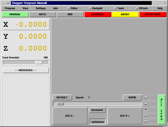
The Mini screen is laid out in several sections. These include a menu across the top, a set of main control buttons just below the menu, and two rather large columns of information that show the state of your machine and allow you to enter commands or programs.
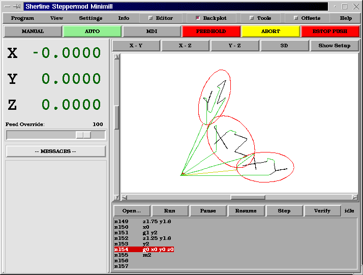
When you compare starting screen with run screen you will see many differences. In the second figure
-
each axis has been homed — the display numbers are dark green
-
the LinuxCNC mode is auto — the auto button has a light green background
-
the backplotter has been turned on — backplot is visible in the pop-in window
-
the tool path from the program is showing in the display.
Once you start working with Mini you will quickly discover how easily it shows the conditions of the LinuxCNC and allows you to make changes to it.
3. Menu Bar
The first row is the menu bar across the top. Here you can configure the screen to display additional information. Some of the items in this menu are very different from what you may be accustomed to with other programs. You should take a few minutes and look under each menu item in order to familiarize yourself with the features that are there.
The menu includes each of the following sections and subsections.
-
Program - This menu includes both reset and exit functions. Reset will return the LinuxCNC to the condition that it was in when it started. Some startup configuration items like the normal program units can be specified in the ini file.
-
View - This menu includes several screen elements that can be added so that you can see additional information during a run. These include
-
Position_Type - This menu item adds a line above the main position displays that shows whether the displays are in inches or metric and whether they are Machine or Relative location and if they are Actual positions or Commanded positions. These can be changed using the Settings menu described below.
-
Tool_Info - This adds a line immediately below the main position displays that shows which tool has been selected and the length of offset applied.
-
Offset_Info - adds a line immediately below the tool info that shows what offsets have been applied. This is a total distance for each axis from machine zero.
-
Show_Restart - adds a block of buttons to the right of the program display in auto mode. These allow the operator to restart a program after an abort or estop. These will pop in whenever estop or abort is pressed but can be shows by the operator anytime auto mode is active by selecting this menu item.
-
Hide_Restart - removes the block of buttons that control the restart of a program that has been aborted or estopped.
-
Show_Split_Right - changes the nature of the right hand column so that it shows both mode and pop-in information.
-
Show_Mode_Full - changes the right hand column so that the mode buttons or displays fill the entire right side of the screen. In manual mode, running with mode full you will see spindle and lube control buttons as well as the motion buttons.
-
Show_Popin_Full - changes the right hand column so that the popin fills the entire right side of the screen.
-
-
Settings - These menu items allow the operator to control certain parameters during a run.
-
Actual_Position - sets the main position displays to actual(machine based) values.
-
Commanded_Position - sets the main position displays to the values that they were commanded to.
-
Machine_Position - sets the main position displays to the absolute distance from where the machine was homed.
-
Relative_Position - sets the main position displays to show the current position including any offsets like part zeros that are active. For more information on offsets see the Coordinate System Chapter.
-
-
Info - lets you see a number of active things by writing their values into the MESSAGE pad.
-
Program_File - will write the currently active program file name.
-
Editor_File - will write the currently active file if the editor pop in is active and a file has been selected for editing.
-
Parameter_File - will write the name of the file being used for program parameters. You can find more on this in the chapters on offsets and using variables for programming.
-
Tool_File - will write the name of the tool file that is being used during this run.
-
Active_G-Codes - will write a list of all of the modal program codes that are active whenever this item is selected. For more information about modal codes see the Modal Groups section.
-
-
Help - opens a text window pop in that displays the contents of the help file.
You will notice between the info menu and the help menu there are a set of four buttons. These are called check buttons because they have a small box that shows red if they have been selected. These four buttons, Editor, Backplot, Tools, and Offsets pop in each of these screens. If more than one pop-in is active (button shown as red) you can toggle between these pop-ins by right clicking your mouse.
4. Control Button Bar
Below the menu line is a horizontal line of control buttons. These are the primary control buttons for the interface. Using these buttons you can change mode from [MANUAL] to [AUTO] to [MDI] (Manual Data Input). These buttons show a light green background whenever that mode is active.
You can also use the [FEEDHOLD], [ABORT], and [ESTOP] buttons to control a programmed move.
4.1. MANUAL
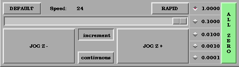
This button or pressing <F3> sets the LinuxCNC to Manual mode and displays an abbreviated set of buttons the operator can use to issue manual motion commands. The labels of the jog buttons change to match the active axis. Whenever Show_Mode_Full is active in in manual mode, you will see spindle and lube control buttons as well as the motion buttons. A keyboard <i> or <I> will switch from continuous jog to incremental jog. Pressing that key again will toggle the increment size through the available sizes.
4.2. AUTO
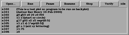
When the Auto button is pressed, or <F4> on the keyboard, and LinuxCNC is set to that mode, a set of the traditional auto operation buttons is displayed, and a small text window opens to show a part program. During run the active line will be displayed as white lettering on a red background.
In the auto mode, many of the keyboard keys are bound to controls. For example, the numbers above the qwerty keys are bound to feed rate override. The 0 sets 100%, 9 sets 90% and such. Other keys work much the same as they do with the tkLinuxCNC graphical interface.
Auto mode does not normally display the active or modal codes. If the operator wishes to check these, use menu Info→Active_G-Codes. This will write all modal codes onto the message scratch pad.
If abort or estop is pressed during a run, a set of buttons will display to the right of the text that allow the operator to shift the restart line forward or backward. If the restart line is not the last active line, it will be highlighted as white letters on a blue background. Caution, a very slow feed rate, and a finger poised over the pause button is advised during any program restart.
4.3. MDI
The MDI button or <F5> sets the Manual Data Input mode. This mode displays a single line of text for block entry and shows the currently active modal codes for the interpreter.
Since many of the keyboard keys are needed for entry, most of the bindings that were available in auto mode are not available here.
4.4. [FEEDHOLD] — [CONTINUE]
Feedhold is a toggle. When the LinuxCNC is ready to handle or is handling a motion command this button shows the feedhold label on a red background. If feedhold has been pressed then it will show the continue label. Using it to pause motion has the advantage of being able to restart the program from where you stopped it. Feedhold will toggle between zero speed and whatever feed rate override was active before it was pressed. This button and the function that it activates is also bound to the pause button on most keyboards.
4.5. [ABORT]
The abort button stops any motion when it is pressed. It also removes the motion command from the LinuxCNC. No further motions are cued up after this button is pressed. If you are in auto mode, this button removes the rest of the program from the motion cue. It also records the number of the line that was executing when it was pressed. You can use this line number to restart the program after you have cleared up the reasons for pressing it.
4.6. [ESTOP]
The estop button is also a toggle but it works in three possible settings.
-
When Mini starts up it will show a raised button with red background with black letters that say ESTOP PUSH. This is the correct state of the machine when you want to run a program or jog an axis. Estop is ready to work for you when it looks like this.
-
If you push the estop button while a motion is being executed, you will see a recessed gray button that says ESTOPPED. You will not be able to move an axis or do any work from the Mini gui when the estop button displays this way. Pressing it with your mouse will return Mini to normal ready condition.
-
A third view is possible here. A recessed green button means that estop has been take off but the machine has not been turned on. Normally this only happens when <F1> estop has been pressed but <F2> has not been pressed.
Joe Martin says, "When all else fails press a software [ESTOP]." This does everything that abort does but adds in a reset so that the LinuxCNC returns to the standard settings that it wakes up on. If you have an external estop circuit that watches the relevant parallel port or DIO pin, a software estop can turn off power to the motors.
5. Left Column
There are two columns below the control line. The left side of the screen displays information of interest to the operator. There are very few buttons to press here.
5.1. Axis Position Displays
The axis position displays work exactly like they do with tkLinuxCNC. The color of the letters is important.
-
Red indicates that the machine is sitting on a limit switch or the polarity of a min or max limit is set wrong in the ini file.
-
Yellow indicates that the machine is ready to be homed.
-
Green indicates that the machine has been homed.
The position can be changed to display any one of several values by using the menu settings. The startup or default settings can be changed in the ini file so these displays wake up just the way that you want them.
5.2. Feed rate Override
Immediately below the axis position displays is the feed rate override slider. You can operate feed rate override and feedhold in any mode of operation. Override will change the speed of jogs or feed rate in manual or MDI modes. You can adjust feed rate override by grabbing the slider with your mouse and dragging it along the groove. You can also change feed rate a percent at a time by clicking in the slider’s groove. In auto mode you can also set feed override in 10% increments by pressing the top row of numbers. This slider is a handy visual reference to how much override is being applied to programmed feed rate.
5.3. Messages
The message display located under the axis positions is a sort of scratch pad for LinuxCNC. If there are problems it will report them there. If you try to home or move an axis when the [ESTOP] button is pressed, you’ll get a message that says something about commanding motion when LinuxCNC is not ready. If an axis faults out for something like falling behind, the message pad will show what happened. If you want to remind an operator to change a tool, for example, you can add a line of code to your program that will display in the message box. An example might be (msg, change to tool #3 and press resume). This line of code, included in a program, will display change to tool #3 and press resume in the message box. The word msg, (with comma included) is the command to make this happen; without msg, the message wouldn’t be displayed. It will still show in the auto modes' display of the program file.
To erase messages simply click the message button at the top of the pad or, on the keyboard, hold down the [Alt] key and press the [m] key.
6. Right Column
The right column is a general purpose place to display and work. Here you can see the modal buttons and text entry or displays. Here you can view a plot of the tool path that will be commanded by your program. You can also write programs and control tools and offsets here. The modal screens have been described above. Each of the popin displays are described in detail below.
6.1. Program Editor
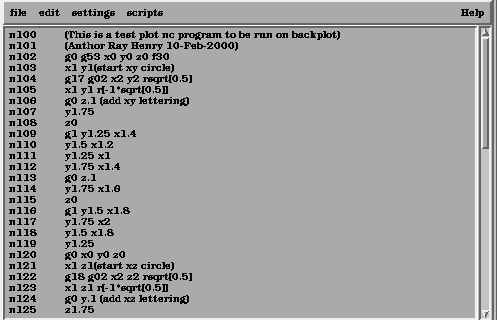
The editor is rather limited compared to many modern text editors. It does not have undo nor paste between windows with the clipboard. These were eliminated because of interaction with a running program. Future releases will replace these functions so that it will work the way you’ve come to expect from a text editor. It is included because it has the rather nice feature of being able to number and renumber lines in the way that the interpreter expects of a file. It will also allow you to cut and paste from one part of a file to another. In addition, it will allow you to save your changes and submit them to the LinuxCNC interpreter with the same menu click. You can work on a file in here for a while and then save and load if the LinuxCNC is in Auto mode. If you have been running a file and find that you need to edit it, that file will be placed in the editor when you click on the editor button on the top menu.
6.2. Backplot Display
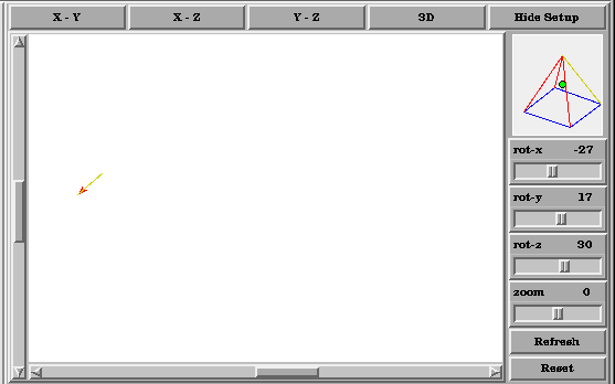
Backplot [Backplot] will show the tool path that can be viewed from a chosen direction. 3-D is the default. Other choices and controls are displayed along the top and right side of the pop-in. If you are in the middle of a cut when you press one of these control buttons the machine will pause long enough to re-compute the view.
Along the right side of the pop-in there is a small pyramid shaped graphic that tries to show the angle you are viewing the tool path from. Below it are a series of sliders that allow you to change the angle of view and the size of the plot. You can rotate the little position angle display with these. They take effect when you press the [Refresh] button. The [Reset] button removes all of the paths from the display and readies it for a new run of the program but retains your settings for that session.
If backplot is started before a program is started, it will try to use some color lines to indicate the kind of motion that was used to make it. A green line is a rapid move. A black line is a feed rate move. Blue and red indicate arcs in counterclockwise and clockwise directions.
The backplotter with Mini allows you to zoom and rotate views after you have run your program but it is not intended to store a tool path for a long period of time.
6.3. Tool Page
The tool page is pretty much like the others. You can set length and diameter values here and they become effective when you press the [Enter] key. You will need to set up your tool information before you begin to run a program. You can’t change tool offsets while the program is running or when the program is paused.
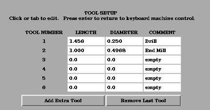
The [Add Tools] and [Remove Tools] buttons work on the bottom of the tool list so you will want to fill in tool information in descending order. Once a new tool has been added, you can use it in a program with the usual G-code commands. There is a 32 tool limit in the current LinuxCNC configuration files but you will run out of display space in Mini long before you get there.
|
Tip
|
You can use Menu > View > Show Popin Full to see more tools if you need. |
6.4. Offset Page
The offset page can be used to display and setup work offsets. The coordinate system is selected along the left hand side of the window. Once you have selected a coordinate system you can enter values or move an axis to a teach position.
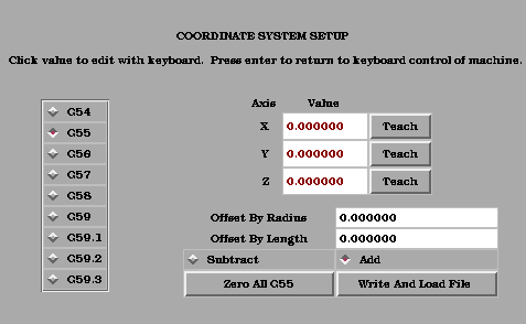
You can also teach using an edgefinder by adding the radius and length to the offset_by widgets. When you do this you may need to add or subtract the radius depending upon which surface you choose to touch from. This is selected with the add or subtract radiobuttons below the offset windows.
The zero all for the active coordinate system button will remove any offsets that you have showing but they are not set to zero in the variable file until you press the write and load file button as well. This write and load file button is the one to use when you have set all of the axis values that you want for a coordinate system.
7. Keyboard Bindings
A number of the bindings used with tkLinuxCNC have been preserved with mini. A few of the bindings have been changed to extend that set or to ease the operation of a machine using this interface. Some keys operate the same regradless of the mode. Others change with the mode that LinuxCNC is operating in.
7.1. Common Keys
-
Pause - Toggle feedhold
-
Escape - abort motion
-
F1 - toggle estop/estop reset state
-
F2 - toggle machine off/machine on state
-
F3 - manual mode
-
F4 - auto mode
-
F5 - MDI mode
-
F6 - reset interpreter
The following only work for machines using auxiliary I/O
-
F7 - toggle mist on/mist off
-
F8 - toggle flood on/flood off
-
F9 - toggle spindle forward/off
-
F10 - toggle spindle reverse/off
-
F11 - decrease spindle speed
-
F12 - increase spindle speed
7.2. Manual Mode
-
1-9 0 - set feed override to 10%-90%, 0 is 100%
-
~ - set feed override to 0 or feedhold
-
x - select X axis
-
y - select Y axis
-
z - select Z axis
-
a - select A axis
-
b - select B axis
-
c - select C axis
-
Left Right Arrow - jog X axis
-
Up Down Arrow - jog Y axis
-
Page Up Down - jog Z axis
-
- _ - jog the active axis in the minus direction
-
+ = - jog the active axis in the plus direction.
-
Home - home selected axis
-
i I - toggle through jog increments
The following only work with a machine using auxiliary I/O
-
b - take spindle brake off
-
Alt-b - put spindle brake on
7.3. Auto Mode
-
1-9,0 - set feed override to 10%-90%, 0 is 100%
-
~ - set feed override to 0 or feedhold
-
o/O - open a program
-
r/R - run an opened program
-
p/P - pause an executing program
-
s/S - resume a paused program
-
a/A - step one line in a paused program
8. Misc
One of the features of Mini is that it displays any axis above number 2 as a rotary and will display degree units for it. It also converts to degree units for incremental jogs when a rotary axis has the focus.