1. Introduction
GMOCCAPY is a GUI for linuxcnc, designed to be used with a touch screen, but can also be used on normal screens with a mouse or hardware buttons and MPG wheels, as it presents HAL Pins for the most common needs. Please find more information in the following.
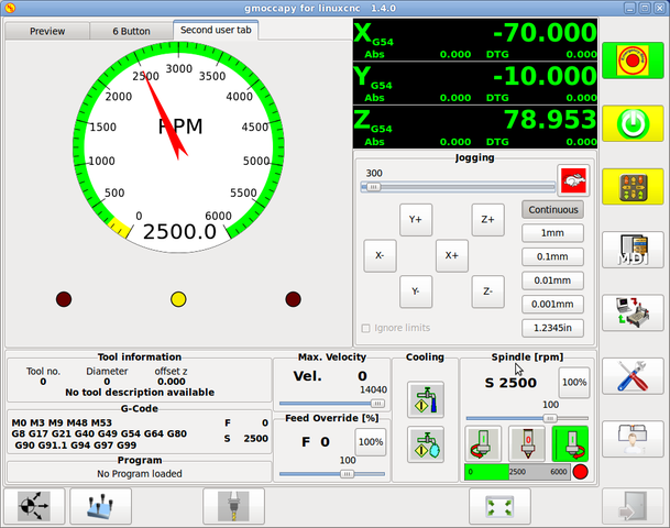
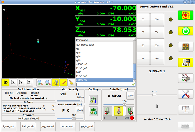
It offers the possibility to display up to 4 axis, support a lathe mode for normal and back tool lathe and can be adapted to nearly every need, because gmoccapy supports embedded tabs and side panels. As a good example for that see gmoccapy_plasma
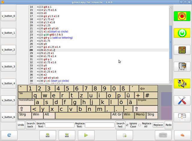
It has support for integrated virtual keyboard (onboard or matchbox-keyboard), so there is no need for a hardware keyboard or mouse, but it can also be used with that hardware. Gmoccapy offers a separate settings page to configure most settings of the GUI without editing files.
gmoccapy can be localized very easy, because the corresponding files are separated from the linuxcnc.po files, so there is no need to translate unneeded stuff. The files are placed in /src/po/gmoccapy. Just copy the gmoccapy.pot file to something like fr.po and translate that file with gtranslator or poedit. After a make you got the GUI in your preferenced language. Please publish your translation, so it can be included in the official packages and be published to other users. At the Moment it is available in English, German, Spanish, Polish, Serbian and Hungarian. Feel free to help me to introduce more languages, nieson@web.de. If you need help, don’t hesitate to ask.
2. Requirements
Gmoccapy has been tested on UBUNTU 10.04 and 12.04 and DEBIAN Wheesy, with LinuxCNC 2.6 ,2.7 , master and machinekit, if you use other versions, please inform about problems or solutions on the forum or the emc-users mailing list
in German Peters CNC Ecke
in English gmoccapy on linuxcnc
The minimum screen resolution for gmoccapy, using it without side panels is 979 x 750 Pixel, so it should fit to every standard screen.
3. How to get gmoccapy
Beginning with LinuxCNC 2.6 gmoccapy is included in the standard installation. So the easiest way to get gmoccapy on you controlling PC, is just to get the actual ISO and install from the CD / DVD /USB-Stick.
If you do have already installed an earlier LinuxCNC version, check how to update here
You will receive updates with the regular deb packages.
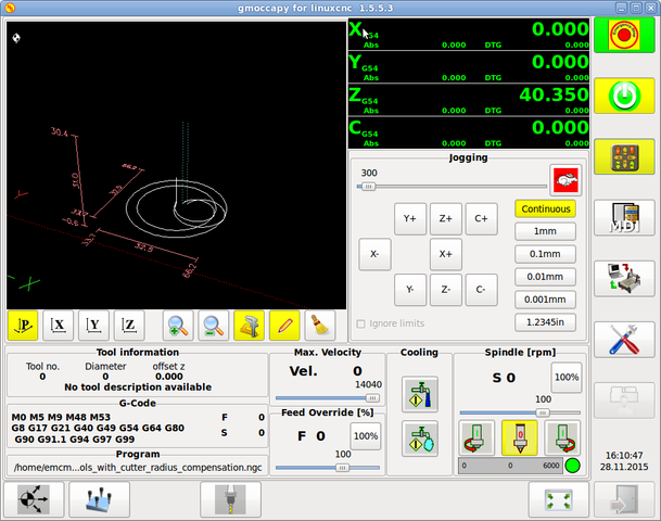
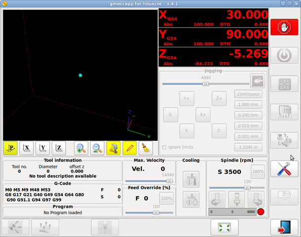
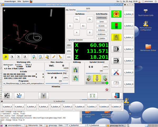
You will get a similar screen to the following: The design may variate depending on your config.
4. Basic configuration
There is really not to much to configure just to run gmoccapy, but there are some points you should take care off if you want to use all the features of the GUI.
You will find the following INI files included, just to show the basics:
* gmoccapy.ini
* gmoccapy_4_axis.ini
* gmoccapy_lathe.ini
* gmoccapy_lathe_imperial.ini
* gmoccapy_left_panel.ini
* gmoccapy_right_panel.ini
* gmoccapy_messages.ini
* gmoccapy_pendant.ini
* gmoccapy_sim_hardware_button.ini
* gmoccapy_tool_sensor.ini
* gmoccapy_with_user_tabs.ini
The names should explain the main intention of the different INI Files.
If you use an existing configuration of your machine, just edit your INI according to this document.
|
Important
|
If you want to use MACROS, don’t forget to set the path to your macros or subroutines folder as described below. |
So let us take a closer look to the the INI file and what you need to include
to use gmoccapy on your machine:
4.1. The DISPLAY Section
[DISPLAY]
DISPLAY = gmoccapy
PREFERENCE_FILE_PATH = gmoccapy_preferences
DEFAULT_LINEAR_VELOCITY = 166.666
MAX_LINEAR_VELOCITY = 166.666
MAX_FEED_OVERRIDE = 1.5
MAX_SPINDLE_OVERRIDE = 1.2
MIN_SPINDLE_OVERRIDE = 0.5
LATHE = 1
BACK_TOOL_LATHE = 1
PROGRAM_PREFIX = ../../nc_files/
The most important part is to tell LinuxCNC to use gmoccapy, editing the [DISPLAY] section.
[DISPLAY]
DISPLAY = gmoccapy
PREFERENCE_FILE_PATH = gmoccapy_preferences
The line PREFERENCE_FILE_PATH gives the location and name of the preferences file to be used. In most cases this line will not be needed, it is used by gmoccapy to store your settings of the GUI, like themes, DRO units, colors, and keyboard settings, etc., see SETTINGS for more details.
|
Note
|
If no path or file is given, gmoccapy will use as default <your_machinename>.pref, if no machine name is given in your INI File it will use gmoccapy.pref The file will be stored in your config dir, so the settings will not be mixed if you use several configs. If you only want to use one file for several machines, you need to include PREFERENCE_FILE_PATH in your INI. |
DEFAULT_LINEAR_VELOCITY = 166.666
Sets the default linear velocity in machine units per second.
|
Note
|
If no value is given, a value of 15 will be applied. If you don’t set max linear velocity, the default linear velocity will be reduced to the default value max linear velocity (60) If you don’t set max velocity in TRAJ, it may be reduced as well see TRAY section |
MAX_LINEAR_VELOCITY = 166.666
Sets the value of the max velocity for jogging in machine units per second.
|
Note
|
If no value is given, a value of 60 will be applied. '' MAX_FEED_OVERRIDE = 1.5 |
Sets the maximum feed override, in the example given, you will be allowed to override the feed by 150% ''
MAX_SPINDLE_OVERRIDE = 1.2
MIN_SPINDLE_OVERRIDE = 0.5
will allow you to change the spindle override within a limit from 50% to 120%
LATHE = 1
BACK_TOOL_LATHE = 1
the first line set the screen layout to control a lathe.
The second line is optional and will switch the X axis in a way you need for a back tool lathe. Also the keyboard shortcuts will react in a different way.
|
Tip
|
See also LATHE specific section |
PROGRAM_PREFIX = ../../nc_files/
Is the entry to tell linuxcnc/gmoccapy where to look for the ngc files,
|
Note
|
if not omitted we will look in the following order: * /linuxcnc/nc_files * / |
You can add embedded programs to gmoccapy like you can do in axis, touchy and gscreen.
All is done by gmoccapy automatically if you include a few lines in your INI file in the DISPLAY section.
If you never used a glade panel, I recommend to read the excellent documentation.
Glade VCP
all you have to take care off, is that you include for every tab or side panel the mentioned three lines,
EMBED_TAB_NAME
represents the name of the tab or side panel,
it is up to you what name you use, but it must be present!
EMBED_TAB_LOCATION
is the place where your program will be placed in the GUI.
valid values are:
see the different INI files included to see the differences
EMBED_TAB_COMMAND
is the command to execute, i.e.
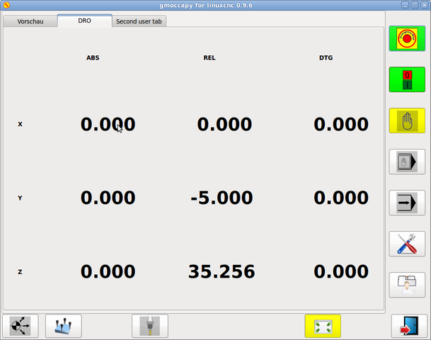
gladevcp -x {XID} dro.glade
includes a custom glade file called dro.glade in the mentioned location
The file must be placed in the config folder of your machine
gladevcp h_buttonlist.glade
will just open a new user window called h_buttonlist.glade
note the difference, this one is stand alone, and can be moved around independent from gmoccapy window
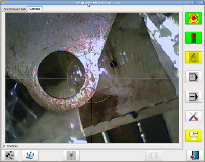
camview-emc -w {XID}
will add a live image from a web cam to the location you specified.
take care that camview-emc is installed, as it is not by default. You find detailed information for camview and linuxcnc at: cam view
gladevcp -c gladevcp -u hitcounter.py -H manual-example.hal manual-example.ui
will add a the panel manual-example.ui, include a custom python handler, hitcounter.py and make all connections after realizing the panel according to manual-example.hal.
here are some examples:
ntb_user_tabs - with integrated camview program
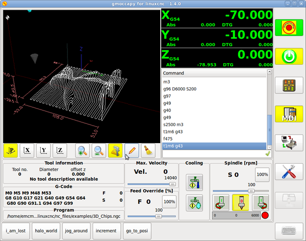
ntb_preview - as maximized version
ntb_preview
box_left - showing gmoccapy in edit mode
box_right - and gmoccapy in MDI mode
Gmoccapy has the ability to create hal driven user messages. To use them you need to introduce some lines in the [DISPLAY] section of the INI file.
Here is how to set up 3 user popup message dialogs the messages support pango markup language. Detailed information about the markup language can be found at Pango Markup
MESSAGE_TEXT    = The text to be displayed, may be pango markup formated+
MESSAGE_TYPE    = "status" , "okdialog" , "yesnodialog"+
MESSAGE_PINNAME = is the name of the hal pin group to be created+
-
status : Will just display a message as popup window, using the messaging system of gmoccapy
-
okdialog : Will hold focus on the message dialog and will activate a "-waiting" Hal_Pin OUT. Closing the message will reset the waiting pin
-
yesnodialog : Will hold focus on the message dialog and will activate a "-waiting" Hal_Pin bit OUT it will also give access to an "-response" Hal_Pin Bit Out, this pin will hold 1 if the user clicks OK, and in all other states it will be 0 Closing the message will reset the waiting pin The response Hal Pin will remain 1 until the dialog is called again
The specific hal pin conventions for these can be found under the User Messages hal pin section
4.2. The RS274NGC Section
[RS274NGC]
SUBROUTINE_PATH = macros
sets the path to search for macros and other subroutines.
4.3. The MACRO Section
You can add macros to gmoccapy, similar to touchy’s way.
A macro is nothing else than a ngc-file. You are able to execute complete
CNC programs in MDI mode, by just pushing one button.
To do so, you have to add a section like so:
[MACROS]
MACRO = i_am_lost
MACRO = halo_world
MACRO = jog_around
MACRO = increment xinc yinc
MACRO = go_to_position X-pos Y-pos Z-pos
This will add 5 macros to the MDI button list. Please note, that maximal 9 macros will appear in the GUI, due to place reasons. But it is no error placing more in your INI file.
The name of the file must be exactly the same as the name given in the MACRO line.
So the macro i_am_lost will call the file i_am_lost.ngc.
The code in between sub and endsub will be executed by pushing the corresponding macro button.
|
Note
|
You will find the sample macros in macros folder placed in the gmoccapy sim folder. |
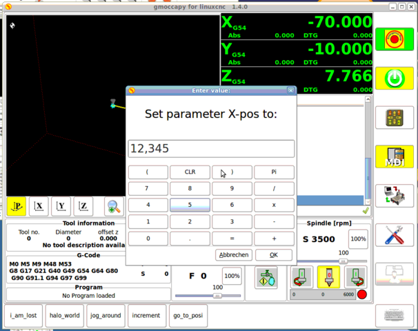
Gmoccapy will also accept macros asking for parameters like:
go_to_position X-pos Y-pos Z-pos
The parameters must be separated by spaces. This calls a file go_to_position.ngc with the following content:
 ; Testfile go to position
 ; will jog the machine to a given position

 O<go_to_position> sub

 G17
 G21
 G54
 G61
 G40
 G49
 G80
 G90

 ;#1 = <X-Pos>
 ;#2 = <Y-Pos>
 ;#3 = <Z-Pos>

 (DBG, Will now move machine to X = #1 , Y = #2 , Z = #3)
 G0 X #1 Y #2 Z #3

 O<go_to_position> endsub
 M2
after pushing the execute macro button, you will be asked to enter the values for X-pos Y-pos Z-pos and the macro will only run if all values have been given.
5. HAL Pins
gmoccapy exports several hal pin to be able to react to hardware devices.
The goal is to get a GUI that may be operated in a tool shop, completely/mostly without mouse or keyboard.
|
Note
|
You will have to do all connections to gmoccapy pins in your postgui.hal file, because they are not available before loading the GUI completely. |
5.1. Right and bottom button lists
The screen has two main button lists, one on the right side an one on the bottom.
The right handed buttons will not change during operation, but the bottom button list will change very often.
The buttons are count from up to down and from left to right beginning with "0".
In hal_show you will see the right (vertical) buttons are:
-
gmoccapy.v-button-0
-
gmoccapy.v-button-1
-
gmoccapy.v-button-2
-
gmoccapy.v-button-3
-
gmoccapy.v-button-4
-
gmoccapy.v-button-5
-
gmoccapy.v-button-6
and the bottom (horizontal) buttons are:
-
gmoccapy.h-button-0
-
gmoccapy.h-button-1
-
gmoccapy.h-button-2
-
gmoccapy.h-button-3
-
gmoccapy.h-button-4
-
gmoccapy.h-button-5
-
gmoccapy.h-button-6
-
gmoccapy.h-button-7
-
gmoccapy.h-button-8
-
gmoccapy.h-button-9
as the buttons in the bottom list will change according the mode and other influences, the hardware buttons will activate different functions, and you don’t have to take care about switching functions around in hal, because that is done completely by gmoccapy!
The sens of this is to be able to use the screen without an touch panel, or protect it from excessive use by placing hardware buttons around the panel.
5.2. Velocities and overrides
All sliders from gmoccapy can be connected to hardware encoder or hardware potmeters.
To connect encoders the following pin are exported:
-
gmoccapy.max-vel-counts = HAL_S32 ; (Maximal Velocity of the machine)
-
gmoccapy.jog-speed-counts = HAL_S32 ; (Jog velocity)
-
gmoccapy.spindle-override-counts = HAL_S32 ; (spindle override)
-
gmoccapy.feed-override-counts = HAL_S32 ; (feed override)
-
gmoccapy.reset-feed-override = HAL_BIT ; (reset the feed override to 100 %)
-
gmoccapy.reset-spindle-override = HAL_BIT ; (reset the spindle override to 100 %)
To connect potmeters, use the following hal pin:
-
gmoccapy.analog-enable = HAL_BIT ; Must be True, to allow analog inputs
-
gmoccapy.jog-vel-value = HAL_FLOAT ; To adjust the jog velocity slider
-
gmoccapy.max-vel-value = HAL_FLOAT ; To adjust the max velocity slider
-
gmoccapy.feed-override-value = HAL_FLOAT ; To adjust the feed override slider
-
gmoccapy.spindle-override-value = HAL_FLOAT ; To adjust the spindle override slider
The float pin do accept values from 0.0 to 1.0, being the percentage value you want to set the slider value.
|
Warning
|
If you use both connection types, do not connect the same slider to both pin, as the influences between the two has not been tested! Different sliders may be connected to the one or other hal connection type. |
|
Important
|
Please be aware, that for the jog velocity depends on the turtle button state, it will lead to different slider scales depending on the mode (turtle or rabbit). Please take also a look to jog velocities and turtle-jog hal pin for more details. |
5.3. jog hal pins
All axis given in the INI File have a jog-plus and a jog-minus pin,
so hardware momentary switches can be used to jog the axis.
For the standard config following hal Pin will be available:
-
gmoccapy.jog-x-plus
-
gmoccapy.jog-x-minus
-
gmoccapy.jog-y-plus
-
gmoccapy.jog-y-minus
-
gmoccapy.jog-z-plus
-
gmoccapy.jog-z-minus
if you use a 4 axis INI file, there will be two additional pins
-
gmoccapy.jog-<your fourth axis letter >-plus
-
gmoccapy.jog-<your fourth axis letter >-minus
for a "C" axis you will see:
-
gmoccapy.jog-c-plus
-
gmoccapy.jog-c-minus
5.4. jog velocities and turtle-jog hal pin
The jog velocity can be selected with the corresponding slider.
The scale of the slider will be modified if the turtle button (the one showing a rabbit or a turtle) has been toggled. If the button is not visible, it might have been disabled on the settings page. If the button shows the rabbit-icon, the scale is from min to max machine velocity. If it shows the turtle, the scale will reach only 1/20 of max velocity by default. The used divider can be set on the settings page.
So using a touch screen it is much easier to select smaller velocities.
5.5. jog increment hal pins
The jog increments are selectable through hal pins, so a select hardware switch can be used to select the increment to use. There will be a maximum of 10 hal pin for the increments given in the INI File, if you give more increments in your INI File, they will be not reachable from the GUI as they will not be displayed.
If you have 6 increments in your hal you will get 7 pins:
-
gmoccapy.jog-inc-0
-
gmoccapy.jog-inc-1
-
gmoccapy.jog-inc-2
-
gmoccapy.jog-inc-3
-
gmoccapy.jog-inc-4
-
gmoccapy.jog-inc-5
-
gmoccapy.jog-inc-6
jog-inc-0 is unchangeable and will represent continuous jogging.
5.6. hardware unlock pin
to be able to use a key switch to unlock the settings page the following pin is exported.
-
gmoccapy.unlock-settings
The settings page is unlocked if the pin is high.
To use this pin, you need to activate it on the settings page.
5.7. Error pins
-
gmoccapy.error
-
gmoccapy.delete-message
gmoccapy.error is an bit out pin, to indicate an error, so a light can lit or even the machine may
be stopped. It will be reseted with the pin gmoccapy.delete-message. gmoccapy.delete-message will
delete the first error and reset the gmoccapy.error pin to False after the last error has been cleared.
|
Note
|
Messages or user infos will not affect the gmoccapy.error pin, but the gmoccapy.delete-message pin will delete the last message if no error is shown! |
5.8. User Created Message HAL Pins
gmoccapy may react to external errors, using 3 different user messages:
All are HAL_BIT pin.
Status
-
gmoccapy.messages.statustest
Yesnodialog
-
gmoccapy.messages.yesnodialog
-
gmoccapy.messages.yesnodialog-waiting
-
gmoccapy.messages.yesnodialog-responce
Okdialog
-
gmoccapy.messages.okdialog
-
gmoccapy.messages.okdialog-waiting
5.9. Spindle feedback pins
There are two pins for spindle feedback
-
gmoccapy.spindle_feedback_bar
-
gmoccapy.spindle_at_speed_led
gmoccapy.spindle_feedback_bar will accept an float input to show the spindle speed
gmoccapy.spindle_at_speed_led is an bit-pin to lit the GUI led if spindle is at speed
5.10. Pins to indicate program progress information
There are three pins giving information over the program progress
-
gmoccapy.program.length = HAL_S32 ; showing the total number of lines of the program
-
gmoccapy.program.current-line = HAL_S32 ; indicating the current working line of the program
-
gmoccapy.program.progress = HAL_FLOAT ; giving the program progress in percentage
The values may not be very accurate, if you are working with subroutines or large remap procedures, also loops will cause different values.
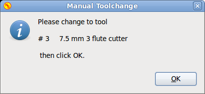
5.11. Tool related pin
This pin are provided to use gmoccapy’s internal tool change dialog, similar to the one known from axis, but with several modifications, so you will not only get the message to change to tool number 3, but also the description of that tool like 7.5 mm 3 flute cutter. The information is taken from the tool table, so it is up to you what to display.
-
gmoccapy.toolchange-number = HAL_S32 ; The number of the tool to be changed
-
gmoccapy.toolchange-change = HAL_BIT ; Indicate that a tool has to be changed
-
gmoccapy.toolchange-changed = HAL_BIT ; Indicate toll has been changed
usually they are connected like this for a manual tool change:
 net tool-change            gmoccapy.toolchange-change    <=   iocontrol.0.tool-change
 net tool-changed           gmoccapy.toolchange-changed   <=   iocontrol.0.tool-changed
 net tool-prep-number       gmoccapy.toolchange-number    <=   iocontrol.0.tool-prep-number
 net tool-prep-loop         iocontrol.0.tool-prepare      <=   iocontrol.0.tool-prepared
This pins allows you to show the active tool offset values for X and Z in the tool information frame.
You should know that they are only active after G43 has been send.
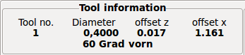
-
gmoccapy.tooloffset-x
-
gmoccapy.tooloffset-z
just connect them like so in your postgui hal.
 net tooloffset-x gmoccapy.tooloffset-x <= motion.tooloffset.x
 net tooloffset-z gmoccapy.tooloffset-z <= motion.tooloffset.z
Please note, that gmoccapy takes care of its own to update the offsets, sending an G43 after any tool change, but not in auto mode!
|
Important
|
So writing a program makes you responsible to include an G43 after each tool change! |
6. Auto Tool Measurement
Gmoccapy offers an integrated auto tool measurement.
To use this feature, you will need to do some additional settings and you may want to use the
offered hal pin to get values in your own ngc remap procedure.
|
Important
|
Before starting the first test, do not forget to enter the Probe height and probe velocities on the settings page! See Settings Page Tool Measurement |
It might be also a good idea to take a look at the tool measurement video: see tool measurement related videos
Tool Measurement in gmoccapy is done a little bit different to many other GUI.
You should follow theese steps:
* touch of you workpiece in X and Y
* measure the hight of your block from the base where your tool switch is located, to the upper face of the block (including chuck etc.)
* Push the button block height and enter the measured value
* Go to auto mode and start your program
here is a small sketch:
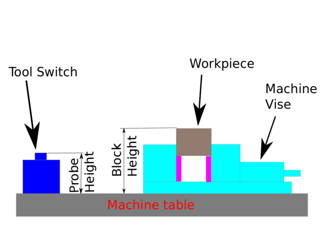
With the first given tool change the tool will be measured and the offset will be set automatically to fit the block height. The advantage of the gmoccapy way is, that you do not need a reference tool.
|
Note
|
Your program must contain a tool change at the beginning! The tool will be measured, even it has been used before, so there is no danger , if the block height has changed. There are several videos showing the way to do that on you tube. |
6.1. Tool measurement pins
Gmoccapy offers 5 pins for tool measurement purpose
The pins are mostly used to be read from a gcode subroutine, so the code can react to different values.
-
gmoccapy.toolmeasurement = HAL_BIT ; enable or not tool measurement
-
gmoccapy.blockheight = HAL_FLOAT ; the measured value of the top face of the workpiece
-
gmoccapy.probeheight = HAL_FLOAT ; the probe switch height
-
gmoccapy.searchvel = HAL_FLOAT ; the velocity to search for the tool probe switch
-
gmoccapy.probevel = HAL_FLOAT ; the velocity to probe tool length
6.2. Tool Measurement INI File modifications
Modify your INI File to include the following:
[RS274NGC]
# Enables the reading of INI and HAL values from gcode
FEATURES=12
# is the sub, with is called when a error during tool change happens
ON_ABORT_COMMAND=O <on_abort> call
# The remap code
REMAP=M6  modalgroup=6 prolog=change_prolog ngc=change epilog=change_epilog
The position of the tool sensor and the start position of the probing movement, all values are absolute coordinates, except MAXPROBE, what must be given in relative movement.
[TOOLSENSOR]
X = 10
Y = 10
Z = -20
MAXPROBE =  -20
this is not named TOOL_CHANGE_POSITION on purpose - canon uses that name and will interfere otherwise
The position to move the machine before giving the change tool command. All values are in absolute coordinates
[CHANGE_POSITION]
X = 10
Y = 10
Z = -2
the Python plugins serves interpreter and task
[PYTHON]
# The path to start a search for user modules
PATH_PREPEND = python
# The start point for all.
TOPLEVEL = python/toplevel.py
6.3. Needed Files
You must copy the following files to your config dir
First make a directory python in your config folder
from your_linuxcnc-dev_directory/configs/sim/gmoccapy/python
Copy toplevel.py to your config_dir/python folder
Copy remap.py to your config_dir/python folder
Copy stdglue.py to your config_dir/python folder
from your_linuxcnc-dev_directory/configs/sim/gmoccapy/macros
copy on_abort.ngc to the directory specified as SUBROUTINE_PATH see RS274NGC Section
from your_linuxcnc-dev_directory/configs/sim/gmoccapy/macros
copy change.ngc to the directory specified as SUBROUTINE_PATH see RS274NGC Section
open change.ngc with a editor and uncomment the following lines (49 and 50):
F #<_hal[gmoccapy.probevel]>
G38.2 Z-4
You may want to modify this file to fit more your needs, feel free, but do not ask for support ;-)
6.4. Needed Hal connections
connect the tool probe in your hal file like so
net probe motion.probe-input <= <your_input_pin>
The line might look like this:
net probe motion.probe-input <= parport.0.pin-15-in
In your postgui.hal file add:
 # The next lines are only needed if the pins had been connected before
 unlinkp iocontrol.0.tool-change
 unlinkp iocontrol.0.tool-changed
 unlinkp iocontrol.0.tool-prep-number
 unlinkp iocontrol.0.tool-prepared

 # link to gmoccapy toolchange, so you get the advantage of tool description on change dialog
 net tool-change            gmoccapy.toolchange-change    <=   iocontrol.0.tool-change
 net tool-changed           gmoccapy.toolchange-changed   <=   iocontrol.0.tool-changed
 net tool-prep-number       gmoccapy.toolchange-number    <=   iocontrol.0.tool-prep-number
 net tool-prep-loop         iocontrol.0.tool-prepare      <=   iocontrol.0.tool-prepared
7. The settings page
To enter the page you will have to click on:

and give an unlock code, witch is 123 as default. If you want to change it at this time you will have to edit the hidden preference file, see the display section for details.
The page looks at the moment like so:
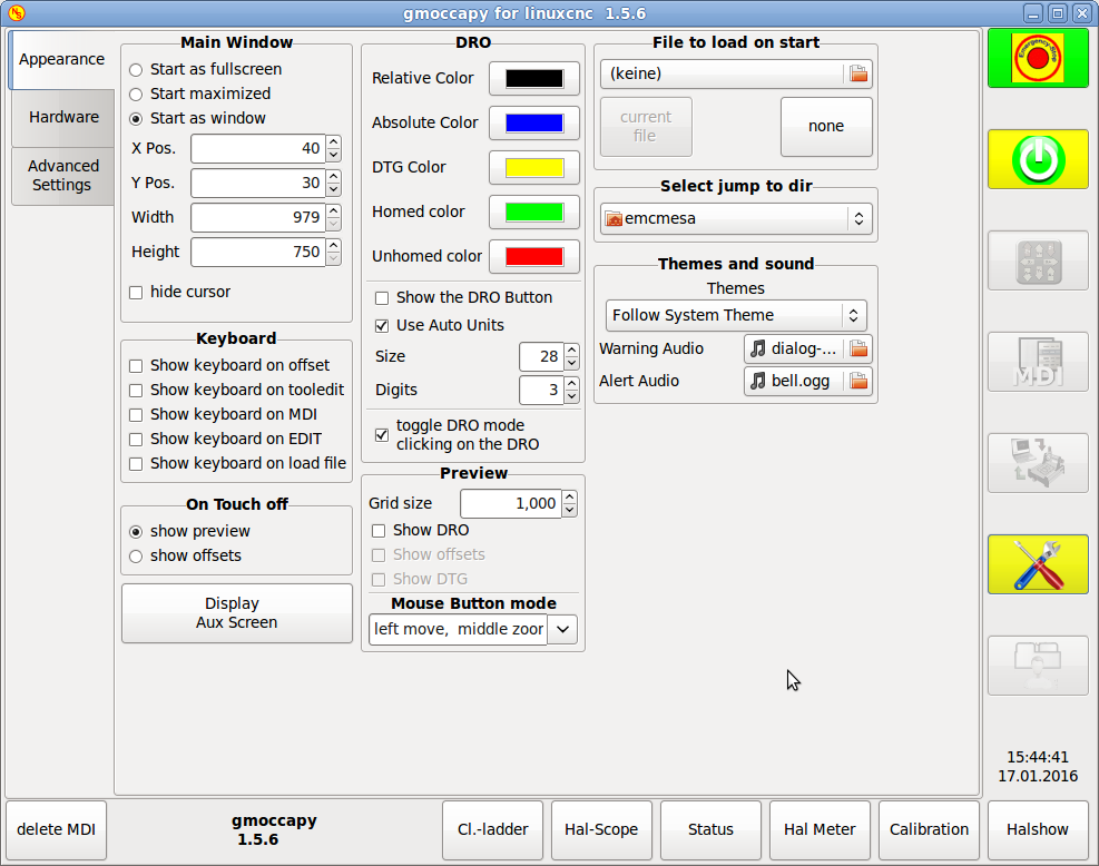
The page is separated in three main tabs:
7.1. Appearance
on this tab you will find the following options:
- Main Window
-
Here you can select how you wish the GUI to start. The main reason for this was the wish to get an easy
way for the user to set the starting options without the need to touch code.
You have three options:
-
start as fullscreen
-
start maximized
-
start as window
If you select start as window the spinboxes to set the position and size will get active.
One time set, the GUI will start every time on the place and with the size selected.
Nevertheless the user can change the size and position using the mouse, but that will
not have any influence on the settings.
-
hide the cursor does allow to hide the cursor, what is very useful if you use a touch screen.
- Keyboard
-
The check-boxes allows the user to select if he want the on board keyboard to be shown immediately,
when entering the MDI Mode, when entering the offset page, the tooledit widget or when open a program
in the EDIT mode. The keyboard button on the bottom button list will not been affected by this settings,
so you be able to show or hide the keyboard by pressing the button. The default behavior will be set by
the check-boxes.
Default are :
-
show keyboard on offset = True
-
show keyboard on tooledit = False
-
show keyboard on MDI = True
-
show keyboard on EDIT = True
-
show keyboard on load file = False
-
|
Note
|
If this section is not sensitive, you have not installed a virtual keyboard, + supported are onboard and matchbox-keyboard. |
If the keyboard layout is not correct, i.e. clicking X gives Z, than the layout has not been set properly,
related to your locale settings.
For onboard it can be solved with a small batch file with the following content:
 #!/bin/bash
 setxkbmap -model pc105 -layout de -variant basic
the letters "de" are for German, you will have to set them according to your locale settings
Just execute this file before starting LinuxCNC, it can be done also adding a starter to your local folder
./config/autostart
so that the layout is set automatically on starting.
For matchbox-keyboard you will have to make your own layout, for a German layout ask in the forum.
- On Touch Off
-
give the option to show the preview tab or the offset page tab if you enter the touch off mode by clicking the corresponding bottom button.
-
show preview
-
show offsets
-
As the notebook tabs are shown, you are able to switch between both views in any case.
- Show Aux Display
-
By clicking this button a additional window will be opened. This button is only sensitive, if a file named gmoccapy2.glade is located in your config folder. You can build the Aux Screen using Glade.
|
Warning
|
The main window of the aux screen must be named window2 |
- DRO Options
-
You have the option to select the background colors of the different DRO states. So users suffering from protanopia (red/green weakness) are able to select proper colors
By default the backgrounds are:
-
Relative mode = black
-
Absolute mode = blue
-
Distance to go = yellow
and the foreground color of the DRO can be selected with:
-
homed color = green
-
unhomed color = red
show dro in preview
the DRO will be shown in the preview window +
show offsets+
the Offsets will be shown in the preview window +
show DTG
the distance to go will be shown in the preview window +
show DRO Button
will allow you to display additional buttons on the left side of the DRO.
It will display:
* one button to switch from relative to absolute coordinates,
* one button to toggle between distance to go and the other states
* and one button to toggle the units from metric to imperial and vice versa.
|
Warning
|
It is not recommended to use this option, because the user will loose the auto unit option, which will toggle the units according to the active gcode G20 / G21 |
|
Note
|
You can change through the DRO modes (absolute, relative, distance to go) by clicking on the DRO! |
Use Auto Units
allows to disable the auto units option of the display, so you can run a program in inches and watch the DRO in mm. +
size
allows to set the size of the DRO font, default is 28, if you use a bigger screen you may want to increase the size up to 56.
If you do use 4 axis, the DRO font size will be 3/4 of the value, because of space reason. +
digits
sets the number of digits of the DRO from 1 to 5.
|
Note
|
Imperial will show one digit more that metric. So if you are in imperial machine units and set the digit value to 1, you will get no digit at all in metric. |
toggle DRO mode
if not active, a mouse click on the DRO will not take any action.
By default this checkbox is active, so every click on any DRO will toogle the DRO readout from actual to relative to DTG (distance to go). +
- Preview
-
Grid Size
Sets the grid size of the preview window.
Unfortunately the size has to be set in inches, even if your machine units are metric. We do hope to fix that in a future release.
Show DRO
Will show the a DRO also in the preview window, it will be shown automatically in fullsize preview
Show DTG
Will show also the DTG (direct distance to end point) in the preview, only if Show DRO is active and
not fullsize preview.
Show Offsets
Will show the offsets in the preview window,
|
Note
|
If you only check this option and leave the others unchecked, you will get in fullsize preview a offset page |
Mouse Button Mode
With this combobox you can select the button behavior of the mouse to rotate, move or zoom within the preview.
-
left rotate, middle move, right zoom
-
left zoom, middle move, right rotate
-
left move, middle rotate, right zoom
-
left zoom, middle rotate, right move
-
left move, middle zoom, right rotate
-
left rotate, middle zoom, right move
Default is left move, middle zoom, right rotate
The mouse wheel will still zoom the preview in every mode.
|
Tip
|
If you select an element in the preview, the selected element will be taken as rotation center point. |
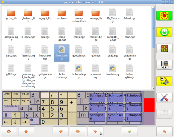
- File to load on start up
-
Select the file you want to be loaded on start up. In other GUI changing this was very cumbersome, because the users where forced to edit the INI File.
If a file is loaded, it can be set by pressing the current button to avoid that any program is loaded at start up, just press the None button.
The file selection screen will use the filters you have set in the INI File, if there aren’t any filters given, you will only see ngc files. The path will be set according to the INI settings in [DISPLAY] PROGRAM_PREFIX
- Jump to dir
-
you can set here the directory to jump to if you press the corresponding button in the file selection dialog.
- Themes and Sounds
-
This lets the user select what desktop theme to apply and what error and messages sounds should be played. By default "Follow System Theme" is set.
7.2. Hardware
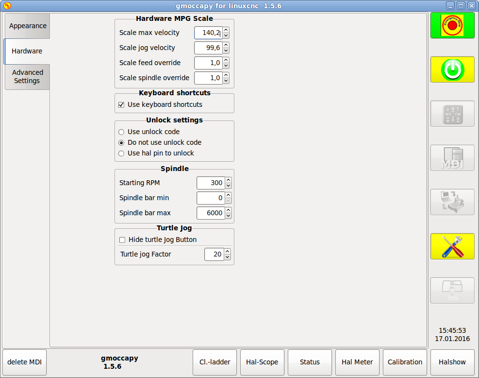
- Hardware MPG Scales
-
For the different Hal Pin to connect MPG Wheels to, you may select individual scales to be applied. The main reason for this was my own test to solve this through hal connections, resulting in a very complex hal file. Imagine a user having an MPG Wheel with 100 ipr and he wants to slow down the max vel from 14000 to 2000 mm/min, that needs 12000 impulses, resulting in 120 turns of the wheel! Or an other user having a MPG Wheel with 500 ipr and he wants to set the spindle override witch has limits from 50 to 120 % so he goes from min to max within 70 impulses, meaning not even 1/4 turn.
By default all scales are set using the calculation:
(MAX - MIN)/100
- Keyboard shortcuts
-
Some users want to jog there machine using the keyboard buttons and there are others that will never allow this. So everybody can select whether to use them or not.
Default is to use keyboard shortcuts.
Please take care if you use a lathe, than the shortcuts will be different. See the Lathe section
-
Arrow Left = X minus
-
Arrow Right = X plus
-
Arrow up = Y plus
-
Arrow Down = Y minus
-
Page Up = Z plus
-
Page Down = Z minus
-
F1 = Estop (will work even if keyboard shortcuts are disabled)
-
F2 = Machine on
-
ESC = Abort
There are additional keys for message handling, see Message behavior and appearance * WINDOWS = Delete last message * <STRG><SPACE> = Delete all messages
- Unlock options
-
you have three options to unlock the settings page:
-
use unlock code (the user must give a code to get in)
-
Do not use unlock code (There will be no security check, not recommended)
-
Use hal pin to unlock (hardware pin must be high to unlock the settings, see hardware unlock pin
-
Default is use unlock code (default = 123)
- Spindle
-
The start RPM sets the rpm to be used if the spindle is started and no S value has been set.
With the MIN and MAX settings you set the limits of the spindle bar shown in the INFO frame on the main screen. It is no error giving wrong values. If you give a maximum of 2000 and your spindle makes 4000 rpm, only the bar level will be wrong on higher speeds than 2000 rpm.
default values are
MIN = 0
MAX = 6000
- Turtle Jog
-
This settings will have influence on the jog velocities.
-
hide turtle jog button will hide the button right of the jog velocity slider, if you hide this button, please take care that it shows the rabbit icon, otherwise you will not be able to jog faster than the turtle jog velocity, which is calculated using the turtle jog factor.
-
Turtle jog factor sets the scale to apply for turtle jog mode. If you set a factor of 20, the max jog velocity will be 1/20 of max velocity of the machine if in turtle mode (button pressed, showing the turtle)
-
|
Note
|
This button can be activated using the turtle-jog hal pin. |
7.3. Advanced Settings
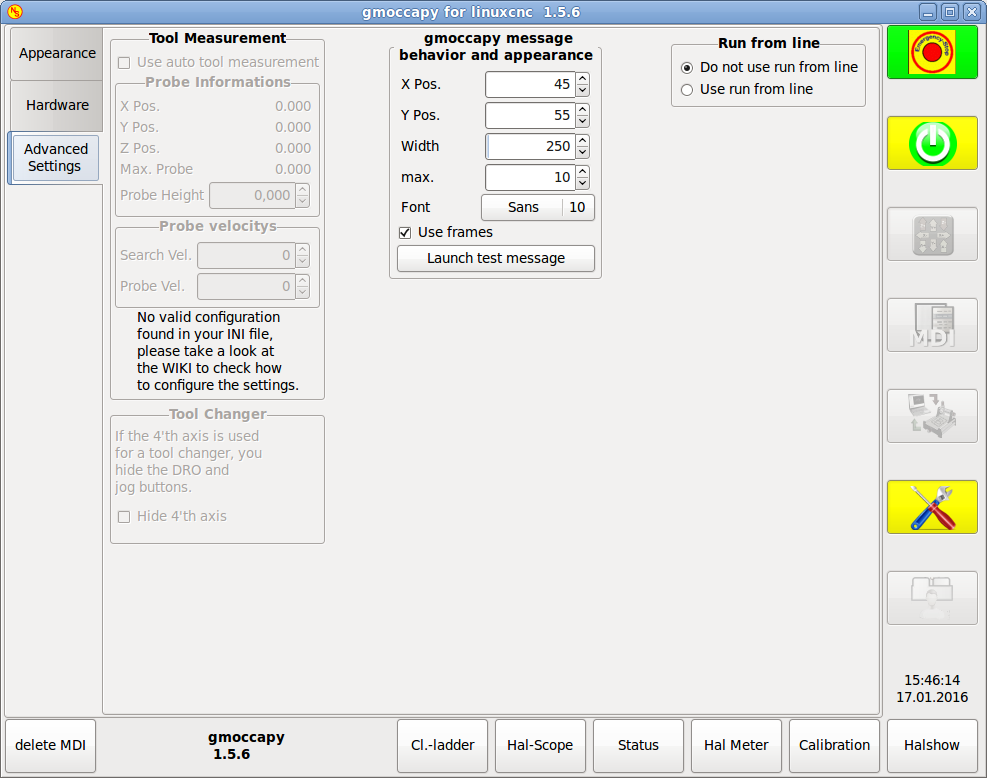
If this part is not sensitive, you do not have a valid INI file configuration to use tool measurement.
Please check Auto Tool Measurement
-
Use auto tool measurement : If checked, after each tool change, a tool measurement will be done, the result will be stored in the tool table and an G43 will be executed after the change.
Probe informations
The following informations are taken from your INI file and must be given in absolute coordinates
-
X Pos. = The X position of the tool switch
-
Y Pos. = The Y position of the tool switch
-
Z Pos. = The X position of the tool switch, we will go as rapid move to this coordinate
-
Max. Probe = is the distance to search for contact, an error will be launched, if no contact is given. The distance has to be given in relative coordinates, beginning the move from Z Pos., so you have to give a negative value to go down!
-
Probe Height = is the height of your probe switch, you can measure it. Just touch off the base, where the probe switch is located and set that to zero. Then make a tool change and watch the tool_offset_z value, that is the hight you must enter here.
Probe velocities
-
Search Vel. = The velocity to search for the tool switch, after contact the tool will go up again and then goes toward the probe again with probe vel, so you will get better results.
-
Probe Vel. = Is the velocity for the second movement to the switch, it should be slower to get better touch results.(In sim mode, this is commented out in macros/change.ngc, otherwise the user would have to click twice on the probe button)
Tool Changer
If your 4’th axis is used in a tool changer, you may want to hide the DRO and all the other buttons
related to that axis.
You can do that by checking the checkbox, that will hide:
-
4’th axis DRO
-
4’th axis Jog button
-
4’th axis home button
-
column of 4’th axis in the offsetpage
-
column of 4’th axis in the tolleditor
This will display small popup windows displaying the message or error text, the behavior is very similar to the one axis uses. You can delete a specific message, by clicking on it’s close button, if you want to delete the last one, just hit the WINDOWS key on your keyboard, or delete all messages at ones with <STRG><SPACE>.
You are able to set some options:
-
X Pos = The position of the top left corner of the message in X counted in pixel from the top left corner of the screen.
-
Y Pos = The position of the top left corner of the message in Y counted in pixel from the top left corner of the screen.
-
Width = The width of the message box
-
max = The maximum messages you want to see at ones, if you set this to 10, the 11th message will delete the first one, so you will only see the last 10 ones.
-
Font = The font and size you want to use to display the messages
-
use frames = If you activate the checkbox, each message will be displayed in a frame, so it is much easiere to distinguish the messages. But you will need a little bit more space.
-
The button launch test message will just do what it is supposed to, it will show a message, so you can see the changes of your settings without the need to generate an error.
You can allow or disallow the run from line. This will set the corresponding button insensitive (grayed out), so the user will not be able to use this option.
|
Warning
|
It is not recommend to use run from line, as LinuxCNC will not take care of any previous lines in the code before the starting line. So errors or crashes are very probably. |
Default is disable run from line
If this button is active, nearly every button press or relevant action of LinuxCNC will be logged in the ALARM history. This is very useful for debugging.
8. LATHE specific section
If in the INI File LATHE = 1 is given, the GUI will change its appearance to the special needs for a lathe. Mainly the Y axis will be hidden and the jog buttons will be arranged in a different order.
Normal Lathe:
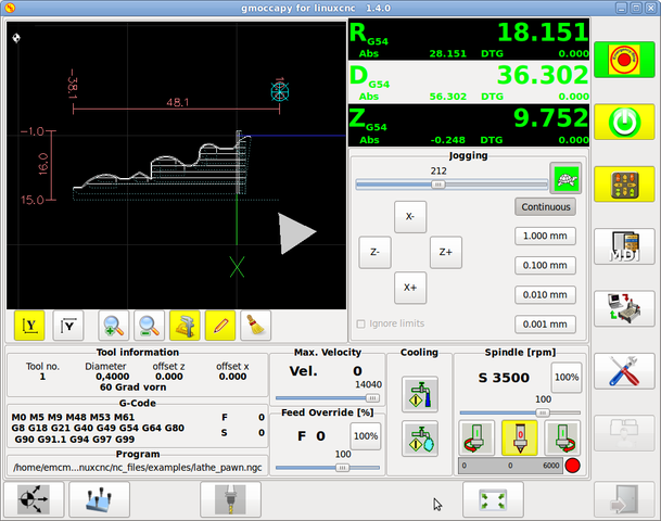
Back Tool Lathe:
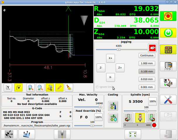
As you see the R DRO has a black background and the D DRO is gray. This will change according to the active G-Code G7 or G8. The active mode is visible by the black background, meaning in the shown images G8 is active.
The next difference to the standard screen is the location of the Jog Button. X and Z have changed places and Y is gone. You will note that the X+ and X- buttons changes there places according to normal or back tool lathe.
Also the keyboard behavior will change:
Normal Lathe:
-
Arrow Left = Z minus
-
Arrow Right = Z plus
-
Arrow up = X minus
-
Arrow Down = X plus
Back Tool Lathe:
-
Arrow Left = Z minus
-
Arrow Right = Z plus
-
Arrow up = X plus
-
Arrow Down = X minus
The tool information frame will show not only the Z offset, but also the X offset and the tool table is showing all lathe relevant information.
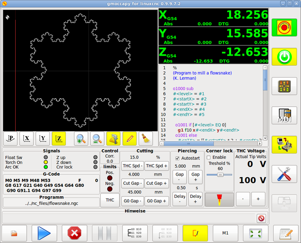
9. Plasma specific section
10. VIDEO on you tube
This are videos showing gmoccapy in action, unfortunately the videos don’t show the latest version of gmoccapy, but the way to use it will not change much in the future. I will try to actualize the videos as soon as possible.
10.1. Basic Usage
German =
English = https://www.youtube.com/watch?v=O5B-s3uiI6g
10.2. Simulated Jog Wheels
English = http://youtu.be/ag34SGxt97o
10.3. Settings Page
German Settings =
English Settings = https://www.youtube.com/watch?v=AuwhSHRJoiI
10.4. Simulated Hardware Button
German Hardware_Button = http://www.youtube.com/watch?v=DTqhY-MfzDE
English Hardware Button = http://www.youtube.com/watch?v=ItVWJBK9WFA
10.5. User Tabs
English User Tabs = http://www.youtube.com/watch?v=rG1zmeqXyZI
10.6. Tool_Measurement_Video
English Auto Tool Measurement Simmulation = http://youtu.be/rrkMw6rUFdk
English Auto Tool Measurement Screen = http://youtu.be/Z2ULDj9dzvk
English Auto Tool Measurement Machine = http://youtu.be/1arucCaDdX4
11. Known problems
11.1. Strange numbers in the info area
If you get strange numbers in the info area of gmoccapy like:
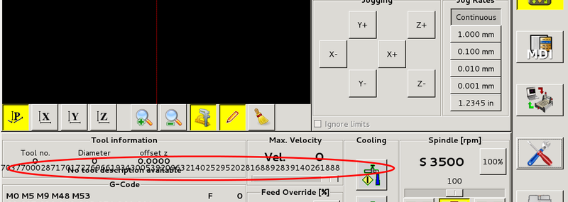
You have made your config file using an older version of StepConfWizard. It has made a wrong entry in the INI file under the [TRAJ] named MAX_LINEAR_VELOCITY = xxx. Change that entry to MAX_VELOCITY = xxx