Canned Cycles G81 through G89 have been implemented for milling. This section describes how each cycle has been implemented. In addition G80 and G98/G99 are considered here because their primary use is related to canned cycles.
All canned cycles are performed with respect to the XY plane. With the current 3 axis interpreter, no A, B, C-axis motion is allowed during canned cycles. Inverse time feed rate is not allowed with cutter radius compensation. Each of the canned cycles defines a new machine motion mode. As a motion mode, they will stay in effect until replaced by another motion G word or by G80 as described below.
All canned cycles use X, Y, R, and Z values in the NC code. These values are used to determine X, Y, R, and Z positions. The R (usually meaning retract) position is along the Z-axis. Some canned cycles use additional arguments that are listed with the specific cycle.
In absolute distance mode, the X, Y, R, and Z values are absolute positions in the current coordinate system. In incremental distance mode, X, Y, and R values are treated as increments to the current position and Z as an increment from the Z-axis position before the move involving Z takes place.
A repeat feature has been implemented. The L word represents the number of repeats. If the repeat feature is used, it is normally used in incremental distance mode, so that the same sequence of motions is repeated in several equally spaced places along a straight line. EMC allows L > 1 in absolute distance mode to mean "do the same cycle in the same place several times." Omitting the L value is equivalent to specifying L=1.
When L>1 in incremental mode, the X and Y positions are determined by adding the given X and Y values either to the current X and Y positions (on the first go-around) or to the X and Y positions at the end of the previous go-around (on the second and successive go-arounds). The R and Z positions do not change during the repeats.
The number of repeats of a canned cycle only works for in the block containing L word. If you want to repeat a canned cycle using the repeat feature by placing a new L word on each line for which you want repeats.
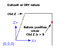
The height of the retract move at the end of each repeat (called "clear Z" in the descriptions below) is determined by the setting of the retract_mode: either to the original Z position (if that is above the R position and the retract_mode is G98, OLD_Z), or otherwise to the R position. (See G98/G99 below)
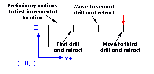
Preliminary motion may be confusing on first read. It should come clear as you work through the examples in G80 and G81 below. Preliminary motion is a set of motions that is common to all of the milling canned cycles. These motions are computed at the time the canned cycle block is encountered by the interpreter. They move the tool into the proper location for the execution of the canned cycle itself.
These motions will be different depending on whether the canned cycle is to be executed using absolute distances or incremental distances. These motions will also be affected by the initial position of the z axis when the canned cycle block is encountered in a program.
If the current Z position is below the R position, the Z axis is traversed to the R position. This happens only once, regardless of the value of L.
In addition, for each repeat as specified by L, one or two moves are made before the rest of the cycle: 1. a straight traverse parallel to the XY-plane to the given XY-position 2. a straight traverse of the Z-axis only to the R position, if it is not already at the R position.
G80 turns off all motion. You should think of it as the off position on a rotary switch where the other positions are the different possible motion modes. In the EMC interpreter, G80 is one of the modal codes so any other code will replace it. The result of the following lines of code is the same.
N1000 G90 G81 X1 Y1 Z1.5 R2.8 (absolute distance canned cycle)
N1001 G80 (turn off canned cycle motion)
N1002 G0 X0 Y0 Z0 (turn on rapid traverse and move to coordinate home)
produces the same final position and machine state as
N1000 G90 G81 X1 Y1 Z1.5 R2.8 (absolute distance canned cycle)
N1001 G0 X0 Y0 Z0 (turn on rapid traverse and move to coordinate home)
The advantage of the first set is that, the G80 line clearly turns off the G81 canned cycle. With the first set of blocks, the programmer must turn motion back on with G0, as is done in the next line, or any other motion mode G word.
Example 1 - Use of a canned cycle as a modal motion code
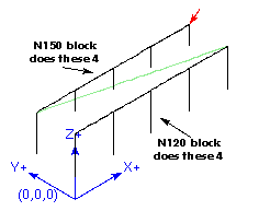
If a canned cycle is not turned off with G80 or another motion word, the canned cycle will attempt to repeat itself using the next block of code that contains an X, Y, or Z word. The following file drills (G81) a set of eight holes as shown. (note the z position change after the first four holes.)
N100 G90 G0 X0 Y0 Z0 (coordinate home)
N110 G1 X0 G4 P0.1
N120 G81 X1 Y0 Z0 R1 (canned drill cycle)
N130 X2
N140 X3
N150 X4
N160 Y1 Z0.5
N170 X3
N180 X2
N190 X1
N200 G80 (turn off canned cycle)
N210 G0 X0 (rapid home moves)
N220 Y0
N220 Z0
N220 M2 (program end)
The use of G80 in line n200 is optional because the G0 on the next line will turn off the G81 cycle. But using the G80. as example 1 shows, will provide for an easily readable canned cycle. Without it, it is not so obvious that all of the blocks between N120 and N200 belong to the canned cycle.
If you use G80 and do not set another modal motion code soon after, you may get one of the following error messages.
Cannot use axis commands with G80
Coordinate setting given with G80
These should serve as a reminder that you need to write in a new motion word.
The G81 cycle is intended for drilling.
0. Preliminary motion, as described above.
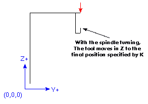
1. Move the Z-axis only at the current feed rate to the Z position.
2. Retract the Z-axis at traverse rate to clear Z. This cycle was used in the description of G80 above but is explained in detail here.
Example 2 - Absolute Position G81
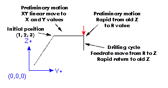
Suppose the current position is (1, 2, 3) and the following line of NC code is interpreted.
G90 G81 G98 X4 Y5 Z1.5 R2.8
This calls for absolute distance mode (G90) and OLD_Z retract mode (G98) and calls for the G81 drilling cycle to be performed once. The X value and X position are 4. The Y value and Y position are 5. The Z value and Z position are 1.5. The R value and clear Z are 2.8. OLD_Z is 3.
The following moves take place.
1. a traverse parallel to the XY plane to (4,5,3)
2. a traverse parallel to the Z-axis to (4,5,2.8).
3. a feed parallel to the Z-axis to (4,5,1.5)
4. a traverse parallel to the Z-axis to (4,5,3)
Example 2 - Absolute Position G81
Suppose the current position is (1, 2, 3) and the following line of NC code is interpreted.
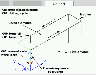
G91 G81 G98 X4 Y5 Z-0.6 R1.8 L3
This calls for incremental distance mode (G91) and OLD_Z retract mode (G98). It also calls for the G81 drilling cycle to be repeated three times. The X value is 4, the Y value is 5, the Z value is -0.6 and the R value is 1.8. The initial X position is 5 (=1+4), the initial Y position is 7 (=2+5), the clear Z position is 4.8 (=1.8+3), and the Z position is 4.2 (=4.8-0.6). OLD_Z is 3.
The first preliminary move is a traverse along the Z axis to (1,2,4.8), since OLD_Z < clear Z.
The first repeat consists of 3 moves.
1. a traverse parallel to the XY-plane to (5,7,4.8)
2. a feed parallel to the Z-axis to (5,7, 4.2)
3. a traverse parallel to the Z-axis to (5,7,4.8) The second repeat consists of 3 moves. The X position is reset to 9 (=5+4) and the Y position to 12 (=7+5).
1. a traverse parallel to the XY-plane to (9,12,4.8)
2. a feed parallel to the Z-axis to (9,12, 4.2)
3. a traverse parallel to the Z-axis to (9,12,4.8) The third repeat consists of 3 moves. The X position is reset to 13 (=9+4) and the Y position to 17 (=12+5).
1. a traverse parallel to the XY-plane to (13,17,4.8)
2. a feed parallel to the Z-axis to (13,17, 4.2)
3. a traverse parallel to the Z-axis to (13,17,4.8)
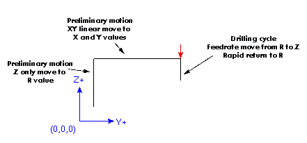
Example 3 - Relative Position G81
Now suppose that you execute the first g81 block of code but from (0, 0, 0) rather than from (1, 2, 3).
G90 G81 G98 X4 Y5 Z1.5 R2.8 Since OLD_Z is below the R value, it adds nothing for the motion but since the initial value of Z is less than the value specified in R, there will be an initial Z move during the preliminary moves.
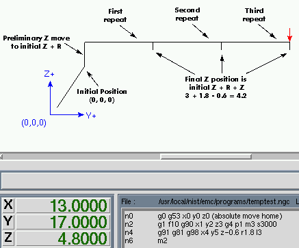
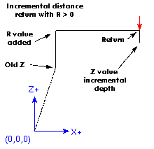
Example 4 - Absolute G81 R > Z
This is a plot of the path of motion for the second g81 block of code.
G91 G81 G98 X4 Y5 Z-0.6 R1.8 L3
Since this plot starts with (0, 0, 0), the interpreter adds the initial Z 0 and R 1.8 and rapids to that location. After that initial z move, the repeat feature works the same as it did in example 3 with the final z depth being 0.6 below the R value.
Example 5 - Relative position R > Z
The G82 cycle is intended for drilling.
0. Preliminary motion, as described above.
1. Move the Z-axis only at the current feed rate to the Z position.
2. Dwell for the given number of seconds.
3. Retract the Z-axis at traverse rate to clear Z. The motion of a G82 canned cycle looks just like g81 with the addition of a dwell at the bottom of the Z move. The length of the dwell is specified by a p# word in the g82 block.
G90 G82 G98 X4 Y5 Z1.5 R2.8 P2
Would be equivalent to example 2 above with a dwell added at the bottom of the hole.
The G83 cycle is intended for deep drilling or milling with chip breaking. The dwell in this cycle causes any long stringers (which are common when drilling in aluminum) to be cut off. This cycle takes a Q value which represents a "delta" increment along the Z-axis. Machinists often refer to this as peck drilling.
0. Preliminary motion, as described above.
1. Move the Z-axis only at the current feed rate downward by delta or to the Z position, whichever is less deep.
2. Dwell for 0.25 second.
3. Retract at traverse rate to clear Z
4. Repeat steps 1 - 3 until the Z position is reached.
5. Retract the Z-axis at traverse rate to clear Z.
NIST lists the elements of the command as G83 X- Y- Z- A- B- C- R- L- Q-
I find this command very handy for many of my deep drilling projects. I have not tried to use the L for a repeat so can't say much about that feature. A typical g83 line that I would write might look like G83 X0.285 Y0.00 Z-0.500 R0.2 L1 Q0.05. EMC moves to position X0.285 Y0.00 at the z height before the block. It then pecks its way down to Z-0.500. Each peck pulls the drill tip up to R0.2 after moving Q0.05.
The G84 cycle is intended for right-hand tapping.
0. Preliminary motion, as described above.
1. Start speed-feed synchronization.
2. Move the Z-axis only at the current feed rate to the Z position.
3. Stop the spindle.
4. Start the spindle counterclockwise.
5. Retract the Z-axis at the current feed rate to clear Z.
6. If speed-feed synch was not on before the cycle started, stop it.
7. Stop the spindle.
8. Start the spindle clockwise.
The G85 cycle is intended for boring or reaming.
0. Preliminary motion, as described above.
1. Move the Z-axis only at the current feed rate to the Z position.
2. Retract the Z-axis at the current feed rate to clear Z. This motion is very similar to g81 except that the tool is retracted from the hole at feed rate rather than rapid.
The G86 cycle is intended for boring.
0. Preliminary motion, as described above.
1. Move the Z-axis only at the current feed rate to the Z position.
2. Dwell for the given number of seconds.
3. Stop the spindle turning.
4. Retract the Z-axis at traverse rate to clear Z.
5. Restart the spindle in the direction it was going. This cycle is very similar to g82 except that it stops the spindle before it retracts the tool and restarts the spindle when it reaches the clearance value R.
The G87 cycle is intended for back boring.
The situation is that you have a through hole and you want to counter bore the bottom of hole. To do this you put an L-shaped tool in the spindle with a cutting surface on the UPPER side of its base. You stick it carefully through the hole when it is not spinning and is oriented so it fits through the hole, then you move it so the stem of the L is on the axis of the hole, start the spindle, and feed the tool upward to make the counter bore. Then you stop the tool, get it out of the hole, and restart it.
This cycle uses I and J values to indicate the position for inserting and removing the tool. I and J will always be increments from the X position and the Y position, regardless of the distance mode setting. This cycle also uses a K value to specify the position along the Z-axis of the top of counterbore. The K value is an absolute Z-value in absolute distance mode, and an increment (from the Z position) in incremental distance mode.
0. Preliminary motion, as described above.
1. Move at traverse rate parallel to the XY-plane to the point indicated by I and J.
2. Stop the spindle in a specific orientation.
3. Move the Z-axis only at traverse rate downward to the Z position.
4. Move at traverse rate parallel to the XY-plane to the X,Y location.
5. Start the spindle in the direction it was going before.
6. Move the Z-axis only at the given feed rate upward to the position indicated by K.
7. Move the Z-axis only at the given feed rate back down to the Z position.
8. Stop the spindle in the same orientation as before.
9. Move at traverse rate parallel to the XY-plane to the point indicated by I and J.
10. Move the Z-axis only at traverse rate to the clear Z.
11. Move at traverse rate parallel to the XY-plane to the specified X,Y location.
12. Restart the spindle in the direction it was going before.
Example 6 - Backbore
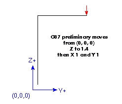
Example six uses a incremental distances from (0, 0, 0) so the preliminary moves look much like those in example five but they are done using the G87 backbore canned cycle.
G91 G87 M3 S1000 X1 Y1 Z-0.4 R1.4 I-0.1 J-0.1 K-0.1
You will notice that the preliminary moves shift the tool to directly above the center axis of the existing bore.
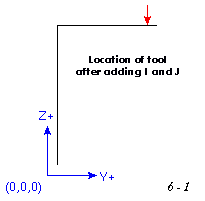
Next it increments that location by the I and J values. I offsets X with a plus value being added to the current X. J does the same for the Y axis.
For our example block both I and J are negative so they move back from the hole axis along the path just made by the tool. The amount of offset required should be just enough that the tool tip will slide down through the bore.
Next the canned cycle moves the tool down in z and at the bottom location represented in the block by the Z 0.4 value it moves the tool back to the center of the bore.
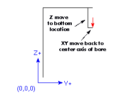
Now the g87 canned cycle turns the spindle on and moves back up into the bore at the programmed feed rate. This is the real cutting action of this canned cycle. With the proper tool in a boring bar this cycle will produce a chamfer on the bottom side of the bore. G87 can also be used to produce a larger diameter bore on the bottom side of the bore.
When the tool has reached the K position it is returned to the bottom location, the spindle is stopped and oriented and follows the earlier path back out of the bore to the initial position above.
This canned cycle assumes spindle orientation which has not been implemented in the EMC to date. The proper alignment of the tool tip to the oriented spindle is critical to the successful insertion of the tool through the hole to be backbored.
The G88 cycle is intended for boring. This cycle uses a P value, where P specifies the number of seconds to dwell.
0. Preliminary motion, as described above.
1. Move the Z-axis only at the current feed rate to the Z position.
2. Dwell for the given number of seconds.
3. Stop the spindle turning.
4. Stop the program so the operator can retract the spindle manually.
5. Restart the spindle in the direction it was going. It is unclear how the operator is to manually move the tool because a change to manual mode resets the program to the top. We will attempt to clarify that step in this procedure.
The G89 cycle is intended for boring. This cycle uses a P value, where P specifies the number of seconds to dwell.
0. Preliminary motion, as described above.
1. Move the Z-axis only at the current feed rate to the Z position.
2. Dwell for the given number of seconds.
3. Retract the Z-axis at the current feed rate to clear Z. This cycle is like G82 except that the tool is drawn back at feed rate rather than rapid.
G98 - initial level return in canned cycles
G99 - R value return in canned cycles
These codes are treated together because they behave very much alike. You will recall that when Z is above R the preparatory move is from the current location to the X, Y values. If G98 is not specified, then the canned cycle will return to the R value rather than the Z value that was used on the approach.
N01 G0 X1 Y2 Z3
N02 G90 G81 X4 Y5 Z-0.6 R1.8 F10
Adding G98 to the second line above means that the return move will be to the value of OLD_Z since it is higher that the R value specified.
Neither code will have any affect when incremental moves with a positive R value are specified because the R value is added to OLD_Z and that result is used as the initial level for a G98. The same value is the computed R value so G99 will also return to the same place.
When the value of R is less than OLD_Z and incremental distance mode is turned on, G98 will return the tool to the value of OLD_Z. Under those conditions G99 will retract the tool to OLD_Z plus the negative R value. The return will be below OLD_Z.
There are at least two reasons for using canned cycles. The first is the economy of code. A single bore would take several lines of code to execute.
Example 1 above demonstrated how a canned cycle could be used to produce 8 holes with ten lines of nc code within the canned cycle mode. The program below will produce the same set of 8 holes using five lines for the canned cycle. It does not follow exactly the same path nor does it drill in the same order as the earlier example. But the program writing economy of a good canned cycle should be obvious.
Example 7 - Eight Holes Revisited
n100 g90 g0 x0 y0 z0 (move coordinate home)
n110 g1 f10 x0 g4 p0.1
n120 g91 g81 x1 y0 z-1 r1 l4(canned drill cycle)
n130 g90 g0 x0 y1
n140 z0
n150 g91 g81 x1 y0 z-.5 r1 l4(canned drill cycle)
n160 g80 (turn off canned cycle)
n170 m2 (program end)
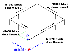
Example 8 - Twelve holes in a square
This example demonstrates the use of the L word to repeat a set of incremental drill cycles for successive blocks of code within the same G81 motion mode. Here we produce 12 holes using five lines of code in the canned motion mode.
N1000 G90 G0 X0 Y0 Z0 (move coordinate home)
N1010 G1 F50 X0 G4 P0.1
N1020 G91 G81 X1 Y0 Z-0.5 R1 L4 (canned drill cycle)
N1030 X0 Y1 R0 L3 (repeat)
N1040 X-1 Y0 L3 (repeat)
N1050 X0 Y-1 L2 (repeat)
N1060 G80 (turn off canned cycle)
N1070 G90 G0 X0 (rapid home)
N1080 Y0
N1090 Z0
N1100 M2 (program end)
The second reason to use a canned cycle is that they all produce preliminary moves and returns that you can anticipate and control regardless of the start point of the canned cycle.