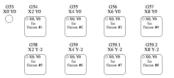
 Figure: Work Offsets
You have seen how handy a tool length offset can be. Having this allows the programmer to ignore the actual tool length when writing a part program. In the same way, it is really nice to be able to find a prominent part of a casting or block of material and work a program from that point rather than having to take account of the location at which the casting or block will be held during the machining.
This chapter introduces you to offsets as they are used by the EMC. These include;
Regardless of any offsets that may be in effect, putting a G53 in a block of code tells the interpreter to go to the real or absolute axis positions commanded in the block. For example
g53 g0 x0 y0 z0
will get you to the actual position where these three axes are zero. You might use a command like this if you have a favorite position for tool changes or if your machine has an auto tool changer. You might also use this command to get the tool out of the way so that you can rotate or change a part in a vice.
G53 is not a modal command. It must be used on each line where motion based upon absolute machine position is desired.
Work or fixture offset are used to make a part home that is different from the absolute, machine coordinate system. This allows the part programmer to set up home positions for multiple parts. A typical operation that uses fixture offsets would be to mill multiple copies of parts on "islands" in a piece, similar to figure [.]
The values for offsets are stored in the VAR file that is requested by the INI file during the startup of an EMC. In our example below we'll use G55. The values for each axis for G55 are stored as variable numbers.
5241 0.000000
5242 0.000000
5243 0.000000
5244 0.000000
5245 0.000000
5246 0.000000
In the VAR file scheme, the first variable number stores the X offset, the second the Y offset and so on for all six axes. There are numbered sets like this for each of the fixture offsets.
Each of the graphical interfaces has a way to set values for these offsets. You can also set these values by editing the VAR file itself and then issuing a [reset] so that the EMC reads the new values. For our example let's directly edit the file so that G55 takes on the following values.
5241 2.000000
5242 1.000000
5243 -2.000000
5244 0.000000
5245 0.000000
5246 0.000000
You should read this as moving the zero positions of G55 to X = 2 units, Y= 1 unit, and Z = -2 units away from the absolute zero position.
Once there are values assigned, a call to G55 in a program block would shift the zero reference by the values stored. The following line would then move each axis to the new zero position. Unlike G53, G54 through G59.3 are modal commands. They will act on all blocks of code after one of them has been set. The program that might be run using figure [.] would require only a single coordinate reference for each of the locations and all of the work to be done there. The following code is offered as an example of making a square using the G55 offsets that we set above.
G55 G0 x0 y0 z0
g1 f2 z-0.2000
x1
y1
x0
y0
g0 z0
g54 x0 y0 z0
m2
“But,” you say, “why is there a G54 in there near the end.” Many programmers leave the G54 coordinate system with all zero values so that there is a modal code for the absolute machine based axis positions. This program assumes that we have done that and use the ending command as a command to machine zero. It would have been possible to use g53 and arrive at the same place but that command would not have been modal and any commands issued after it would have returned to using the G55 offsets because that coordinate system would still be in effect.
One other variable in the VAR file becomes important when we think about offset systems. This variable is named 5220. In the default files its value is set to 1.00000. This means that when the EMC starts up it should use the first coordinate system as its default. If you set this to 9.00000 it would use the nineth offset system as its default for startup and reset. Any value other than an interger (decimal really) between 1 and 9 will cause the EMC to fault on startup.
In the general programming chapter we listed a G10 command word. This command can be used to change the values of the offsets in a coordinate system. (add here)
The way that it works has changed just a bit from the early days to the current releases. It should be thought of as a temporary offset that is applied to all other offsets.
This set of commands include;
When the commands are used as described above, they will work pretty much as you would expect.
A user must understand the correct ways that the g92 values work. They are set based upon the location of each axis when the g92 command is invoked. The NIST document is clear that, “To make the current point have the coordinates” x0, y0, and z0 you would use g92 x0 y0 z0. G92 does not work from absolute machine coordinates. It works from current location.
G92 also works from current location as modified by any other offsets that are in effect when the g92 command is invoked. While testing for differences between work offsets and actual offsets it was found that a g54 offset could cancel out a g92 and thus give the appearance that no offsets were in effect. However, the g92 was still in effect for all coordinates and did produce expected work offsets for the other coordinate systems.
It is likely that the absence of home switches and proper home procedures will result in very large errors in the application of g92 values if they exist in the var file. Many EMC users do not have home switches in place on their machines. For them home should be found by moving each axis to a location and issuing the home command. When each axis is in a known location, the home command will recalculate how the g92 values are applied and will produce consistent results. Without a home sequence, the values are applied to the position of the machine when the EMC begins to run.
There are at least two ways to set G92 values.
Both of these work from the current location of the axis to which the offset is to be applied.
Issuing g92 x y z a b c does in fact set values to the g92 variables such that each axis takes on the value associated with its name. These values are assigned to the current position of the machine axis. These results satisfy paragraphs one and two of the NIST document.
G92 commands work from current axis location and add and subtract correctly to give the current axis position the value assigned by the g92 command. The effects work even though previous offsets are in.
So if the X axis is currently showing 2.0000 as its position a G92 x0 will set an offset of -2.0000 so that the current location of X becomes zero. A G92 X2 will set an offset of 0.0000 and the displayed position will not change. A G92 X5.0000 will set an offset of 3.0000 so that the current displayed position becomes 5.0000.
Sometimes the values of a G92 offset will remain in the VAR file. This can happen when a file is aborted during processing that has G92 offsets in effect. When this happens reset or a startup will cause them to become active again. The variables are named
5211 0.000000
5212 0.000000
5213 0.000000
5214 0.000000
5215 0.000000
5216 0.000000
where 5211 is the X axis offset and so on. If you are seeing unexpected positions as the result of a commanded move, or unexpected numbers in the position displays when you start up, issue a G92.1 in the MDI widow the problems should go away.
With these tests we can see that reset returns g92 to the condition that it had when the interpreter started up. The reader should note that we have established ... that no write of these values occurs during a normal run so if no g92 was set at the startup, none will be read in during a reset.
It may be that this is the heart of the problem that some have experienced with differences between the old and the new interpreter. It may well be, but I leave it to others to test, that the old interpreter and task programs immediately wrote values to the var file and then found those values during a reset.
On the other hand, if G92 values existed in the VAR file when the EMC started up
... starting the EMC with g92 values in the var file is that it will apply the values to current location of each axis. If this is home position and home position is set as machine zero everything will be correct. Once home has been established using real machine switches or moving each axis to a known home position and issuing an axis home command, g92 commands and values work as advertised.
These tests did not study the effect of re-reading the var file while they contain numbers. This could cause problems if g92 offsets had been removed with g92.1 but the var file still contained the previous numbers.
It is this complexity that causes us to say that G92 values must be treated as temporary. They should be used to set global short term offsets. The G54-59.3 coordinate systems should be used whenever long lasting and predictable offsets are needed.
This sample engraving project mills a set of four .1 radius circles in roughly a star shape around a center circle. We can setup the individual circle pattern like this.
G10 L2 P1 x0 y0 z0 (ensure that g54 is set to machine zero)
g0 x-.1 y0 z0
g1 f1 z-.25
g3 x-.1 y0 i.1 j0
g0 z0
m2
We can issue a set of commands to create offsets for the four other circles like this.
G10 L2 P2 x0.5 (offsets g55 x value by 0.5 inch)
G10 L2 P3 x-0.5 (offsets g56 x value by -0.5 inch)
G10 L2 P4 y0.5 (offsets g57 y value by 0.5 inch)
G10 L2 P5 y-0.5 (offsets g58 y value by -0.5 inch)
We put these together in the following program.
(a program for milling five small circles in a diamond shape)
G10 L2 P1 x0 y0 z0 (ensure that g54 is machine zero)
G10 L2 P2 x0.5 (offsets g55 x value by 0.5 inch)
G10 L2 P3 x-0.5 (offsets g56 x value by -0.5 inch)
G10 L2 P4 y0.5 (offsets g57 y value by 0.5 inch)
G10 L2 P5 y-0.5 (offsets g58 y value by -0.5 inch)
g54 g0 x-.1 y0 z0 (center circle)
g1 f1 z-.25
g3 x-.1 y0 i.1 j0
g0 z0
g55 g0 x-.1 y0 z0 (first offset circle)
g1 f1 z-.25
g3 x-.1 y0 i.1 j0
g0 z0
g56 g0 x-.1 y0 z0 (second offset circle)
g1 f1 z-.25
g3 x-.1 y0 i.1 j0
g0 z0
g57 g0 x-.1 y0 z0 (third offset circle)
g1 f1 z-.25
g3 x-.1 y0 i.1 j0
g0 z0
g58 g0 x-.1 y0 z0 (fourth offset circle)
g1 f1 z-.25
g3 x-.1 y0 i.1 j0
g54 g0 x0 y0 z0
m2
Now comes the time when we might apply a set of G92 offsets to this program. You'll see that it is running in each case at z0. If the mill were at the zero position, a g92 z1.0000 issued at the head of the program would shift everything down an inch. You might also shift the whole pattern around in the XY plane by adding some x and y offsets with g92. If you do this you should add a G92.1 command just before the m2 that ends the program. If you do not, other programs that you might run after this one will also use that g92 offset. Furthermore it would save the g92 values when you shut down the EMC and they will be recalled when you start up again.