Mesa 5i25+7i77 plug-n-go configuration
24 May 2014 08:48 #47272
by 33zy
Replied by 33zy on topic Mesa 5i25+7i77 plug-n-go configuration
Regarding field inputs, I am working the home circuit, currently I have 15 amps, and I am going to use a resistor to take that down to one amp for the 7i77. I don't see a max amperage for inputs, what value is other builders using safely with the 7i77?
Please Log in or Create an account to join the conversation.

24 May 2014 09:03 #47273
by andypugh
This whole question seems wrong to me.
The inputs are safe to a voltage, I assume this means that they have their own current-limiting resistors, but I really want to understand your question better.
Replied by andypugh on topic Mesa 5i25+7i77 plug-n-go configuration
Regarding field inputs, I am working the home circuit, currently I have 15 amps, and I am going to use a resistor to take that down to one amp for the 7i77. I don't see a max amperage for inputs, what value is other builders using safely with the 7i77?
This whole question seems wrong to me.
The inputs are safe to a voltage, I assume this means that they have their own current-limiting resistors, but I really want to understand your question better.
Please Log in or Create an account to join the conversation.

24 May 2014 09:54 #47274
by PCW
Replied by PCW on topic Mesa 5i25+7i77 plug-n-go configuration
The 7I77 field inputs sense +DC voltage and expect that the input will come
from the field power source (Usually 12 or 24VDC )
so for a home switch the normal wiring would be:
+24VDC field power --> SWITCH --> 7I77 INPUT
The input resistance is 22K Ohms and the input threshold is set to about 1/2
the field voltage
from the field power source (Usually 12 or 24VDC )
so for a home switch the normal wiring would be:
+24VDC field power --> SWITCH --> 7I77 INPUT
The input resistance is 22K Ohms and the input threshold is set to about 1/2
the field voltage
Please Log in or Create an account to join the conversation.
20 Oct 2014 21:59 #52207
by 33zy
Replied by 33zy on topic Mesa 5i25+7i77 plug-n-go configuration
Just a quick logic check.
I set up the circuit to give:
>14.4v nominal
<9.6v when the home switch is deployed
Is that correct or do I have it backwards?
I set up the circuit to give:
>14.4v nominal
<9.6v when the home switch is deployed
Is that correct or do I have it backwards?
Please Log in or Create an account to join the conversation.
20 Oct 2014 22:28 #52210
by PCW
Replied by PCW on topic Mesa 5i25+7i77 plug-n-go configuration
Those thresholds are correct for 24V field power
but as I said before, switch wiring would normally be:
+24 VDC field power --> SWITCH --> 7I77 INPUT
No need to make it more complicated than this.
For limit switches, Normally Closed (NC) is preferred
so you would use the hm2_5i25.0.7i77.0.0.input-xx-not pins
that will be "true" when a NC limit switch is depressed.
Your question about home power scares me a little,
no 120V power should be anywhere near the
control electronics (the Field IO is 10 to 32V DC only)
Please Log in or Create an account to join the conversation.
20 Oct 2014 23:06 #52212
by 33zy
Replied by 33zy on topic Mesa 5i25+7i77 plug-n-go configuration
My apoligies, I will clarify.
I am using 24volt field power, as described in the line below.
+24 vdc field power -->switch ---->7i77 input
I did not realize we could change the Hal file to reverse the logic, with "not" command added at the end of input definition
For limit then;
1) Hal file input is defined with "not"
2) when input senses nothing or ground = true
Wire switch to normally be field power , and to zero when limit deployed
Thank you for your patience
Please Log in or Create an account to join the conversation.
20 Oct 2014 23:14 #52213
by andypugh
Just to clarify, the -not is not a "command". Each physical input has two HAL pins, one which indicates the input, and one that indicates the inverse of the input.
It is possible to use both, if required.
Replied by andypugh on topic Mesa 5i25+7i77 plug-n-go configuration
I did not realize we could change the Hal file to reverse the logic, with "not" command added at the end of input definition
Just to clarify, the -not is not a "command". Each physical input has two HAL pins, one which indicates the input, and one that indicates the inverse of the input.
It is possible to use both, if required.
Please Log in or Create an account to join the conversation.
20 Oct 2014 23:38 - 21 Oct 2014 00:10 #52218
by PCW
Replied by PCW on topic Mesa 5i25+7i77 plug-n-go configuration
The "not" in the name is not a hal command but rather the signal ending in -not is a separate signal
Many hal input signals are provided in both polarities as a convenience
Yep
Many hal input signals are provided in both polarities as a convenience
2) when input senses nothing or ground = true
Wire switch to normally be field power , and to zero when limit deployed
Yep
Last edit: 21 Oct 2014 00:10 by PCW. Reason: clarify
Please Log in or Create an account to join the conversation.
01 Dec 2014 02:12 - 02 Dec 2014 04:27 #53547
by 33zy
Hello,
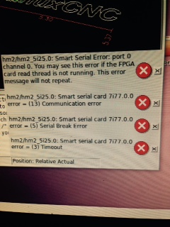
I am getting some errors at startup, curious if anyone might be able to point me in the correct direction. The error code has good information I do not have the expertise currently to decipher.
I am at the early stages and trying to setup just one axis, could this be a problem in my hal file, or does it sound more like hardware?
I am using the 5v from 5i25
I have 24v field power
(error 1)
hm2/hm2_5i25.0: Smart Serial Error: port 0 channel 0. You may see this error if the FPGA card read thread is not running. This error message will not repeat.
(error 2)
hm2/hm2_5i25.0: Smart serial card 7i77.0.0 error = (13) Communication error
(error 3)
hm2/hm2_5i25.0: Smart serial card 7i77.0.0 error = (3) Timeout
problem resolved:
After using a new cable from the 7i77 to 5i25 these errors ceased. 12/1/2014
Replied by 33zy on topic Mesa 5i25+7i77 plug-n-go configuration
Hello,
I am getting some errors at startup, curious if anyone might be able to point me in the correct direction. The error code has good information I do not have the expertise currently to decipher.
I am at the early stages and trying to setup just one axis, could this be a problem in my hal file, or does it sound more like hardware?
I am using the 5v from 5i25
I have 24v field power
(error 1)
hm2/hm2_5i25.0: Smart Serial Error: port 0 channel 0. You may see this error if the FPGA card read thread is not running. This error message will not repeat.
(error 2)
hm2/hm2_5i25.0: Smart serial card 7i77.0.0 error = (13) Communication error
(error 3)
hm2/hm2_5i25.0: Smart serial card 7i77.0.0 error = (3) Timeout
problem resolved:
After using a new cable from the 7i77 to 5i25 these errors ceased. 12/1/2014
Last edit: 02 Dec 2014 04:27 by 33zy.
Please Log in or Create an account to join the conversation.
01 Dec 2014 02:45 #53549
by PCW
Replied by PCW on topic Mesa 5i25+7i77 plug-n-go configuration
This suggests a power supply issue of some kind since it looks like communication to the field I/O section
of the 7I77 was lost at startup
I would verify that the 7i77 logic 5V supply is correct (4.5V minimum 5.5V maximum)
The check that the field I/O power is OK (8V minimum 32V maximum <0.5V ripple)
a shorted output and a weak field supply might cause this error also
of the 7I77 was lost at startup
I would verify that the 7i77 logic 5V supply is correct (4.5V minimum 5.5V maximum)
The check that the field I/O power is OK (8V minimum 32V maximum <0.5V ripple)
a shorted output and a weak field supply might cause this error also
Please Log in or Create an account to join the conversation.
Moderators: cmorley
Time to create page: 0.108 seconds