4th axis as lathe spindle: question about index

13 Oct 2014 17:17 #52006
by andypugh
The HAL pins are 32-bit, but the internal counters are 64-bit. You won't see an overflow this lifetime.
Replied by andypugh on topic 4th axis as lathe spindle: question about index
BTW: what about the signed 32-bit counter inside the (software/mesa) encoder components? What happens if that one overflows?
The HAL pins are 32-bit, but the internal counters are 64-bit. You won't see an overflow this lifetime.
Please Log in or Create an account to join the conversation.
13 Oct 2014 17:24 - 13 Oct 2014 17:24 #52009
by DaBit
Replied by DaBit on topic 4th axis as lathe spindle: question about index
That's great news!.
With the intended 1:3 speed reduction of the servo and 2500 lines encoder I expected I needed a restart of LinuxCNC after 2^31 / (say 1500rpm times 30k counts per revolution) = only 48 minutes of constant rotation....
With the intended 1:3 speed reduction of the servo and 2500 lines encoder I expected I needed a restart of LinuxCNC after 2^31 / (say 1500rpm times 30k counts per revolution) = only 48 minutes of constant rotation....
Last edit: 13 Oct 2014 17:24 by DaBit.
Please Log in or Create an account to join the conversation.
13 Oct 2014 17:31 #52011
by cncbasher
Replied by cncbasher on topic 4th axis as lathe spindle: question about index
DaBit
i would be interested in trying your 4th axis component etc
if theirs anything specific that needs testing , glad to help
i would be interested in trying your 4th axis component etc
if theirs anything specific that needs testing , glad to help
Please Log in or Create an account to join the conversation.
13 Oct 2014 17:35 #52013
by DaBit
Replied by DaBit on topic 4th axis as lathe spindle: question about index
OK, I'll post the component and the snippet of HAL configuration here later.
Please Log in or Create an account to join the conversation.
14 Oct 2014 19:34 #52088
by DaBit
Replied by DaBit on topic 4th axis as lathe spindle: question about index
Sorry for the delay; life got in the way. But as a bonus, I wrote a bit of documentation.
The component can be found here: millturn_helper.comp
(right click, Save As)
Installation:
1) If you don't already have the development tools you might need to install them using 'sudo apt-get install linuxcnc-dev'
2)Open a terminal and go to the directory where you saved the .comp file
3) sudo comp --install millturn_helper.comp
4) comp --document millturn_helper.comp
5) man ./millturn_helper.9
6) Change your configuration according to the documentation
The man page:
MILLTURN_HELPER(9)                                HAL Component                               MILLTURN_HELPER(9)


NAME
       millturn_helper  -  Helper component to faciliate using a rotary A/B/C axis as constant velocity rotating
       device to faciliate mill/turn setups

SYNOPSIS
       loadrt millturn_helper [count=N|names=name1[,name2...]]

DESCRIPTION
       millturn_helper is a helper component that allows free switching of a rotary axis between  regular  posi‐
       tioning mode and and a "lathe" mode where the rotary axis rotates at a given speed. When switching modes,
       the motion is controlled in such a way that the transition is seamless.  To be able to do this, the  com‐
       ponent  must  be  placed  between "motion", the rotary axis positioning servoloop/stepper and the spindle
       control.


OPERATION MODES
       Three modes are supported, which can be set using the mode pin of the component.

       mode 0: The millturn_helper component is transparent, and both the rotary axis and main spindle behave as
       usual

       mode  1: The rotary axis rotates with the speed given by the secondary_spindle_speed pin (and speed-scale
       parameter). The main spindle behaves as usual, thus an Sxxxx command affects  main  spindle  speed.  This
       mode does not allow spindle synchronised moves and while in this mode the affected rotary axis should not
       be programmed from within NGC code.

       mode 2: The functions of the rotary axis and main spindle are swapped. The rotary axis now reacts to main
       spindle  commands  (Sxxxx,  M3,  M4,  etc.).  The  main  spindle rotates with the speed given by the sec‐
       ondary_spindle_speed pin (and speed-scale parameter). Since the rotary axis becomes the main spindle this
       mode allows spindle synchronised moves, CSS, etcetera. While in this mode the affected rotary axis should
       not be programmed from within NGC code.


EXAMPLE
       The following piece of HAL file and script may serve as an example.

       # ################
       # Mill/turn helper component to allow A-axis to function as lathe
       # ################
       setp millturn-helper.0.joint-max-acceleration [AXIS_3]MAX_ACCELERATION
       setp millturn-helper.0.joint-max-velocity [AXIS_3]MAX_VELOCITY
       # The speed scale is used to go from rev/min to units/sec
       setp millturn-helper.0.speed-scale 6
       # And we need to know the unit system. Standard is degrees: 360 per rev.
       setp millturn-helper.0.units-per-rev 360

       net apos-cmd-in axis.3.motor-pos-cmd => millturn-helper.0.position-cmd
       net apos-fb-out millturn-helper.0.position-fb => axis.3.motor-pos-fb
       net millturn-helper-mode millturn-helper.0.mode
       net millturn-helper-secspindlespeed millturn-helper.0.secondary-spindle-speed
       net millturn-helper-isbusy millturn-helper.0.is-busy

       net a-pos-cmd   millturn-helper.0.joint-position-cmd => hm2_5i25.0.stepgen.01.position-cmd
       net a-pos-fb    hm2_5i25.0.stepgen.01.position-fb => millturn-helper.0.joint-position-fb

       A very basic M-code script to allow changing modes from within G-code could be like this. Save this in  a
       file  called M120 (or any other M101-M199 number) in your USER_M_PATH. Usage from within NGC code is then
       "M120 P<0|1|2> Q<secondary spindle speed>". A real script should do at least a bit more error checking.

       #!/bin/bash
       s_mode=$1
       s_rpm=$2
       while [ "$(halcmd -s gets millturn-helper-isbusy)" = "TRUE" ]; do
               sleep 1s
       done
       halcmd sets millturn-helper-mode $s_mode
       halcmd sets millturn-helper-secspindlespeed $s_rpm
       while [ "$(halcmd -s gets millturn-helper-isbusy)" = "TRUE" ]; do
               sleep 1s
       done
       exit 0


BUGS
       Currently mode 2 is not yet operational. The author has to build a 4th axis first :)


FUNCTIONS
       millturn-helper.N (requires a floating-point thread)


PINS
       millturn-helper.N.position-cmd float in
              Position command coming from motion

       millturn-helper.N.position-fb float out
              Position feedback command to motion

       millturn-helper.N.joint-position-cmd float out
              Position command towards servo/stepper

       millturn-helper.N.joint-position-fb float in
              Position feedback from servo/stepper

       millturn-helper.N.m-spindle-forward bit in
              spindle-forward from motion

       millturn-helper.N.m-spindle-reverse bit in
              spindle-reverse from motion

       millturn-helper.N.m-spindle-on bit in
              spindle-on from motion

       millturn-helper.N.m-spindle-speed-out float in
              spindle-speed-out from motion. Note that this name differs from the motion pin

       millturn-helper.N.m-spindle-at-speed bit out
              spindle-at-speed to motion

       millturn-helper.N.m-spindle-speed-in float out
              spindle-speed-in to motion

       millturn-helper.N.m-spindle-revs float out
              spindle-revs to motion

       millturn-helper.N.spindle-forward bit out
              spindle-forward command to spindle

       millturn-helper.N.spindle-reverse bit out
              spindle-reverse command to spindle

       millturn-helper.N.spindle-on bit out
              spindle-on command to spindle

       millturn-helper.N.spindle-speed-out float out
              spindle-speed-out command to spindle

       millturn-helper.N.spindle-at-speed bit in
              spindle-at-speed command coming from spindle

       millturn-helper.N.spindle-speed-in float in
              spindle-speed-in from spindle encoder

       millturn-helper.N.spindle-revs float in
              spindle-revs to motion

       millturn-helper.N.mode u32 in
              Operational mode. 0=axis and spindle operate as usual, no change  in  functionality.  1=rotational
              axis rotates with speed given in secondary-spindle-speed, main spindle behaves as regular. 2=rota‐
              tional axis becomes the main spindle, the real spindle rotates with the speed given in  secondary-
              spindle-speed

       millturn-helper.N.secondary-spindle-speed float in
              Velocity of the secondary spindle, scaled by speed-scale. Negative numbers mean CW, positive CCW

       millturn-helper.N.reverse-spindledir bit in
              When TRUE, inverts the rotation direction of the secondary spindle

       millturn-helper.N.is-busy bit out
              When  TRUE,  the  component  is finishing up an operation and G-code execution should be suspended
              until this flag becomes FALSE again

PARAMETERS
       millturn-helper.N.joint-max-velocity float rw (default: 1.0)
              Maximum velocity of the joint in units/second. Usually equal to [AXIS_n]MAX_VELOCITY

       millturn-helper.N.joint-max-acceleration float rw (default: 1.0)
              Maximum acceleration of the joint in units/second^2. Usually equal to [AXIS_n]MAX_ACCELERATION

       millturn-helper.N.speed-scale float rw (default: 6.0)
              Speed scale used to convert secondary-spindle-speed to units per second. When  units  are  degrees
              and the input speed is rpm this number must be 6.0 since 1rpm equals 6 degrees per second

       millturn-helper.N.units-per-rev float rw (default: 360.0)
              Number of units per full revolution

       millturn-helper.N.dbg-pos-offset float r
       millturn-helper.N.dbg-curr-spindle-speed float r
       millturn-helper.N.dbg-state u32 r
       millturn-helper.N.dbg-acc float r
       millturn-helper.N.dbg-fperiod float r
       millturn-helper.N.dbg-dist float r

AUTHOR
       DaBit (dabitATicecoldcomputingDOTcom)

LICENSE
       GPL


LinuxCNC Documentation                             2014-10-14                                 MILLTURN_HELPER(9)
Please Log in or Create an account to join the conversation.
14 Oct 2014 23:09 #52096
by cncbasher
Replied by cncbasher on topic 4th axis as lathe spindle: question about index
thanks for posting , really looking forward to seeing how this all comes together .
Dave
Dave
Please Log in or Create an account to join the conversation.
15 Oct 2014 03:25 #52106
by akb1212
Replied by akb1212 on topic 4th axis as lathe spindle: question about index
We can only hope you get a 4th axis built soon then ")
I came to think of a couple of things about this..... LinuxCNC have a lathe mode. I'm not to familiar with what the difference is compared to milling mode since I haven't looked at it. But I assume the tool shape and such things are implemented differently in lathe mode.
It would possibly also be a good idea to make the preview window change to lathe view, or even better, make a new view that is adapted to millturn. I haven't seen how this is handled by the commercial controls, but I imagine some of you guys know how this is normally done.
DaBit,
What are your plans/thoughts on speed range on your 4th axis? Available torque will obviously have to be compromised in regards to max RPM on your lathe. Are you thinking of using two (or more) gears like Simpson36 are using? His setup require a manual gear change. This will obviously make you loose position when you change gear. If you don't apply the brake on the spindle while you make the gear change that is.
Nevertheless, a manual gear change isn't ideal. But space and size might limit automatic gear changes and make it impractical and difficult to make.
Anyway, if a gear is implemented in any way on the 4th axis this will have to be considered when using this module. And the gear range and the way it's changed will most likely be different from gear change on the main mill spindle. In particular since the lowest speed you want for 4th axis to have is a lot lower than you would want you main milling spindle to have.
Most of these things aren't problems that will be handled directly by the new component you are making. Although they will have to be dealt with since the gearing of the main spindle will change as a result of using this new component. At least with mode 2.
There are probably also other side effects of mode 2 that will have to be considered. We would most definitely want a spindle brake on the 4th axis.
Come to think of it, it would probably also be a good idea to install a spindle brake on the main milling spindle as well if the lathe tooling is to be held in it. It might be a good idea to attach them elsewhere on the spindle head like Simpson36 have done on his mill (which is in fact quite clever and makes it possible to have many tools available in an efficient manner). But I imagine its a good idea to be able to have the lathe tools in the main spindle too. And I know my mill will have to have a spindle brake to be able to handle that. And since I have an ATC it makes more sense to use the main milling spindle as main lathe tool holder as well. Then I will be able to use the ATC for lathe operations as well.
Anyway, the spindle brake logic could possibly be implemented in to the milturn helper component? There need to be some logic to handle this as the axes are swapped.
Sorry for this rambling. But there are loads of details that comes up when I start to think of how to implement all of this.
But thanks again for sharing this. There are so many possibilities that opens up with this....
Anders
Please Log in or Create an account to join the conversation.
15 Oct 2014 04:50 #52107
by DaBit
Replied by DaBit on topic 4th axis as lathe spindle: question about index
First I'll have to finish the mill itself 
It spent the last two evenings milling the work area flat (and it is not even done yet). I do this very slowly by taking a pass and waiting a few minutes; if the temperature of the surface rises while the bottom is still cold it will warp. Until now there are not many surprises, which is a good thing. After that I have a couple of other jobs to do to, but then I will continue with the 4th axis.
For that 4th axis I have a 1.1kW/3000rpm servo motor with 2500 lines encoder. In positioning mode it can do 3000rpm, but in (analog) velocity mode it should be capable of doing a bit more with loss of torque; I can set the maximum velocity up to 5000rpm. I am thinking of gearing it down 1:3 or 1:4 using a wide steel-reinforced toothed belt with large pulleys. That way I can do ~1250rpm or ~14Nm of torque. Should be sufficient; most of my turning needs involve POM, aluminium and brass or small diameter steel. I also need a fairly large/heavy chuck to match the inertia of the chuck to the servo. Even then I think positioning is not stiff enough for 4-axis milling (there must be a reason why everybody gears down that 4th axis 1:100 or so), but since most 4-axis milling can be done using simple indexing, a brake should take care of that.
But I suppose that leaving a little space for a second set of pulleys and an encoder on the main spindle is not such a bad idea
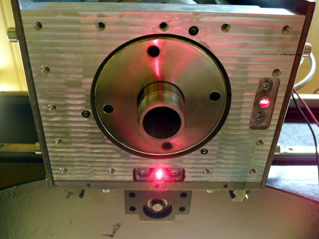
I intend to mount the lathe tooling to the Z-axis column itself, not in the spindle. I drilled a bunch of holes in the bottom plate just for the 'I want to hang something on the column, now where do I attach it?':
I think that handling the brakes is best left to one or more external components instead of one big monolithic millturn-helper component. That allows easier tailoring to a certain situation.
Having LinuxCNC swap display modes and possibly the meaning of the X and Z axes when the component is activated is also not very high on my priority list. Personally I don't need it when using mixed mode since the NGC code for that is most likely handcrafted anyway. And if I intend to do turning only I might as well start another configuration.
It spent the last two evenings milling the work area flat (and it is not even done yet). I do this very slowly by taking a pass and waiting a few minutes; if the temperature of the surface rises while the bottom is still cold it will warp. Until now there are not many surprises, which is a good thing. After that I have a couple of other jobs to do to, but then I will continue with the 4th axis.
For that 4th axis I have a 1.1kW/3000rpm servo motor with 2500 lines encoder. In positioning mode it can do 3000rpm, but in (analog) velocity mode it should be capable of doing a bit more with loss of torque; I can set the maximum velocity up to 5000rpm. I am thinking of gearing it down 1:3 or 1:4 using a wide steel-reinforced toothed belt with large pulleys. That way I can do ~1250rpm or ~14Nm of torque. Should be sufficient; most of my turning needs involve POM, aluminium and brass or small diameter steel. I also need a fairly large/heavy chuck to match the inertia of the chuck to the servo. Even then I think positioning is not stiff enough for 4-axis milling (there must be a reason why everybody gears down that 4th axis 1:100 or so), but since most 4-axis milling can be done using simple indexing, a brake should take care of that.
But I suppose that leaving a little space for a second set of pulleys and an encoder on the main spindle is not such a bad idea
I intend to mount the lathe tooling to the Z-axis column itself, not in the spindle. I drilled a bunch of holes in the bottom plate just for the 'I want to hang something on the column, now where do I attach it?':
I think that handling the brakes is best left to one or more external components instead of one big monolithic millturn-helper component. That allows easier tailoring to a certain situation.
Having LinuxCNC swap display modes and possibly the meaning of the X and Z axes when the component is activated is also not very high on my priority list. Personally I don't need it when using mixed mode since the NGC code for that is most likely handcrafted anyway. And if I intend to do turning only I might as well start another configuration.
Please Log in or Create an account to join the conversation.

20 Oct 2014 04:36 - 20 Oct 2014 04:44 #52200
by roschi
Replied by roschi on topic 4th axis as lathe spindle: question about index
Hi,
maybe my approach can give some more ideas hints. -->
4th axis with no trivial kins module
I have modified the rt module 'encoder' to my needs. As a result the index-enable pin works like the example for lathe synchronized motions.
I have realised a switch to change the control mode of the 4th servo from velocity mode to position control mode. (EtherCAT Drive profile CIA 402)
Spindle related pins AND axis related pins are always connected. The drive ignores them based on the choosen mode.
A disadvantage is that if you programm a M3 and the 4th axis is switched to be a A axes no error results.
The main milling spindle is control over custom M functions (M103, M104, M105)
I have also modified the G33 function meens the source file control.c to have synchronized spindle motion along X-Axis and constant surface speed along Z-Axis.
(see:
Kind regards
Andreas
source files: github.com/aschiffler/linuxcnc
Last edit: 20 Oct 2014 04:44 by roschi.
Please Log in or Create an account to join the conversation.
20 Oct 2014 05:06 #52201
by DaBit
Replied by DaBit on topic 4th axis as lathe spindle: question about index
I still did not dive deeper into the index-enable/lathe mode thing. Have to finish the mill first and build a 4th axis to have decent test hardware. I pulled the development a bit forward because someone else needed it, and in it's current state it is useable for him.
But modifyling the LinuxCNC core like you did with G33 is not something I intend to do. That makes doing a fresh git pull quite an adventure. It should be very well possible to do all this without modifying LinuxCNC.
But modifyling the LinuxCNC core like you did with G33 is not something I intend to do. That makes doing a fresh git pull quite an adventure. It should be very well possible to do all this without modifying LinuxCNC.
Please Log in or Create an account to join the conversation.
Time to create page: 0.093 seconds