LinuxCNC can control up to 8 spindles. The number is set in the INI file. The examples below all refer to a single-spindle config with spindle control pins with names like spindle.0... In the case of a multiple spindle machine all that changes is that additional pins exist with names such as spindle.6...
1. 0-10 Volt Spindle Speed
If your spindle speed is controlled by an analog signal, (for example, by a VFD with a 0 V to 10 V signal) and you’re using a DAC card like the m5i20 to output the control signal:
First you need to figure the scale of spindle speed to control signal, i.e. the voltage. For this example the spindle top speed of 5000 RPM is equal to 10 Volts.
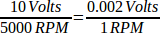
We have to add a scale component to the HAL file to scale the spindle.N.speed-out to the 0 to 10 needed by the VFD if your DAC card does not do scaling.
loadrt scale count=1
addf scale.0 servo-thread
setp scale.0.gain 0.002
net spindle-speed-scale spindle.0.speed-out => scale.0.in
net spindle-speed-DAC scale.0.out => <your DAC pin name>
2. PWM Spindle Speed
If your spindle can be controlled by a PWM signal, use the pwmgen component to create the signal:
loadrt pwmgen output_type=0
addf pwmgen.update servo-thread
addf pwmgen.make-pulses base-thread
net spindle-speed-cmd spindle.0.speed-out => pwmgen.0.value
net spindle-on spindle.0.on => pwmgen.0.enable
net spindle-pwm pwmgen.0.pwm => parport.0.pin-09-out
# Set the spindle's top speed in RPM
setp pwmgen.0.scale 1800
This assumes that the spindle controller’s response to PWM is simple: 0% PWM gives 0 RPM, 10% PWM gives 180 RPM, etc. If there is a minimum PWM required to get the spindle to turn, follow the example in the nist-lathe sample configuration to use a scale component.
3. Spindle Enable
If you need a spindle enable signal, link your output pin to spindle.0.on. To link these pins to a parallel port pin put something like the following in your .hal file, making sure you pick the pin that is connected to your control device.
net spindle-enable spindle.0.on => parport.0.pin-14-out
4. Spindle Direction
If you have direction control of your spindle, then the HAL pins spindle.N.forward and spindle.N.reverse are controlled by the G-codes M3 and M4. Spindle speed Sn must be set to a positive non-zero value for M3/M4 to turn on spindle motion.
To link these pins to a parallel port pin, put something like the following in your .hal file making sure you pick the pin that is connected to your control device.
net spindle-fwd spindle.0.forward => parport.0.pin-16-out
net spindle-rev spindle.0.reverse => parport.0.pin-17-out
5. Spindle Soft Start
If you need to ramp your spindle speed command and your control does not have that feature it can be done in HAL. Basically you need to hijack the output of spindle.N.speed-out and run it through a limit2 component with the scale set so it will ramp the rpm from spindle.N.speed-out to your device that receives the rpm. The second part is to let LinuxCNC know when the spindle is at speed so motion can begin.
In the 0-10 Volt example the line
net spindle-speed-scale spindle.0.speed-out => scale.0.in
is changed as shown in the following example:
In case you have not run across them before, here’s a quick introduction to the two HAL components used in the following example.
-
A limit2 is a HAL component (floating point) that accepts an input value and provides an output that has been limited to a max/min range, and also limited to not exceed a specified rate of change.
-
A near is a HAL component (floating point) with a binary output that says whether two inputs are approximately equal.
More info is available in the documentation for HAL components, or from the man pages, just say man limit2 or man near in a terminal.
# load the real time modules limit2 and near with names so it is easier to follow their connections
loadrt limit2 names=spindle-ramp
loadrt near names=spindle-at-speed

# add the functions to a thread
addf spindle-ramp servo-thread
addf spindle-at-speed servo-thread

# set the parameter for max rate-of-change
# (max spindle accel/decel in units per second)
setp spindle-ramp.maxv 60

# hijack the spindle speed out and send it to spindle ramp in
net spindle-cmd <= spindle.0.speed-out => spindle-ramp.in

# the output of spindle ramp is sent to the scale in
net spindle-ramped <= spindle-ramp.out => scale.0.in

# to know when to start the motion we send the near component
# (named spindle-at-speed) to the spindle commanded speed from
# the signal spindle-cmd and the actual spindle speed
# provided your spindle can accelerate at the maxv setting.
net spindle-cmd => spindle-at-speed.in1
net spindle-ramped => spindle-at-speed.in2

# the output from spindle-at-speed is sent to spindle.0.at-speed
# and when this is true motion will start
net spindle-ready <= spindle-at-speed.out => spindle.0.at-speed
6. Spindle Feedback
6.1. Spindle Synchronized Motion
Spindle feedback is needed by LinuxCNC to perform any spindle coordinated motions like threading and constant surface speed. LinuxCNC can perform synchronized motion and CSS with any of up to 8 spindles. Which spindles are used is controlled from G-code. CSS is possible with several spindles simultaneously.
The StepConf Wizard can perform the connections for a single-spindle configuration for you if you select Encoder Phase A and Encoder Index as inputs.
Hardware assumptions for this example:
-
An encoder is connected to the spindle and puts out 100 pulses per revolution on phase A.
-
The encoder A phase is connected to the parallel port pin 10.
-
The encoder index pulse is connected to the parallel port pin 11.
Basic Steps to add the components and configure them:
[In this example, we will assume that some encoders have already
been issued to axes/joints 0, 1, and 2. So the next encoder available
for us to attach to the spindle would be number 3. Your situation may
differ.]
[The HAL encoder index-enable is an exception to the rule in
that it behaves as both an input and an output, see the
Encoder Section for details]
[It is because we selected non-quadrature simple counting…
above that we can get away with quadrature counting without having any
B quadrature input.]
# Add the encoder to HAL and attach it to threads.
loadrt encoder num_chan=4
addf encoder.update-counters base-thread
addf encoder.capture-position servo-thread

# Set the HAL encoder to 100 pulses per revolution.
setp encoder.3.position-scale 100

# Set the HAL encoder to non-quadrature simple counting using A only.
setp encoder.3.counter-mode true

# Connect the HAL encoder outputs to LinuxCNC.
net spindle-position encoder.3.position => spindle.0.revs
net spindle-velocity encoder.3.velocity => spindle.0.speed-in
net spindle-index-enable encoder.3.index-enable <=> spindle.0.index-enable

# Connect the HAL encoder inputs to the real encoder.
net spindle-phase-a encoder.3.phase-A <= parport.0.pin-10-in
net spindle-phase-b encoder.3.phase-B
net spindle-index encoder.3.phase-Z <= parport.0.pin-11-in
6.2. Spindle At Speed
To enable LinuxCNC to wait for the spindle to be at speed before executing a series of moves, the spindle.N.at-speed needs to turn true at the moment the spindle is at the commanded speed. To achieve this you need spindle feedback from an encoder. Since the feedback and the commanded speed are not usually exactly the same you should to use the near component to determine that the two numbers are close enough.
The connections needed are from the spindle velocity command signal to near.n.in1 and from the spindle velocity from the encoder to near.n.in2. Then the near.n.out is connected to spindle.N.at-speed. The near.n.scale needs to be set to say how close the two numbers must be before turning on the output. Depending on your setup you may need to adjust the scale to work with your hardware.
The following is typical of the additions needed to your HAL file to enable Spindle At Speed. If you already have near in your HAL file then increase the count and adjust code to suit. Check to make sure the signal names are the same in your HAL file.
# load a near component and attach it to a thread
loadrt near
addf near.0 servo-thread

# connect one input to the commanded spindle speed
net spindle-cmd => near.0.in1

# connect one input to the encoder-measured spindle speed
net spindle-velocity => near.0.in2

# connect the output to the spindle-at-speed input
net spindle-at-speed spindle.0.at-speed <= near.0.out

# set the spindle speed inputs to agree if within 1%
setp near.0.scale 1.01