1. AXIS
To create a PyVCP panel to use with the AXIS interface that is attached to the right of AXIS you need to do the following basic things.
-
Create an XML file that contains your panel description and put it in your config directory.
-
Add the PyVCP entry to the [DISPLAY] section of the INI file with your XML file name.
-
Add the POSTGUI_HALFILE entry to the [HAL] section of the INI file with the name of your postgui HAL file name.
-
Add the links to HAL pins for your panel in the postgui.hal file to connect your PyVCP panel to LinuxCNC.
2. Floating Panels
To create floating PyVCP panels that can be used with any interface you need to do the following basic things.
-
Create an XML file that contains your panel description and put it in your config directory.
-
Add a loadusr line to your HAL file to load each panel.
-
Add the links to HAL pins for your panel in the postgui.hal file to connect your PyVCP panel to LinuxCNC.
The following is an example of a loadusr command to load two PyVCP panels and name each one so the connection names in HAL will be known.
loadusr -Wn btnpanel pyvcp -c btnpanel panel1.xml
loadusr -Wn sppanel pyvcp -c sppanel panel2.xml
The -Wn makes HAL Wait for name to be loaded before proceeding.
The pyvcp -c makes PyVCP name the panel.
The HAL pins from panel1.xml will be named btnpanel.<_pin name_>.
The HAL pins from panel2.xml will be named sppanel.<_pin name_>.
Make sure the loadusr line is before any nets that make use of the PyVCP pins.
3. Jog Buttons Example
In this example we will create a PyVCP panel with jog buttons for X, Y, and Z. This configuration will be built upon a StepConf Wizard generated configuration. First we run the StepConf Wizard and configure our machine, on the Advanced Configuration Options page we then make a couple of selections to add a blank PyVCP panel as shown in the following figure. For this example we named the configuration pyvcp_xyz on the Basic Machine Information page of the StepConf Wizard.
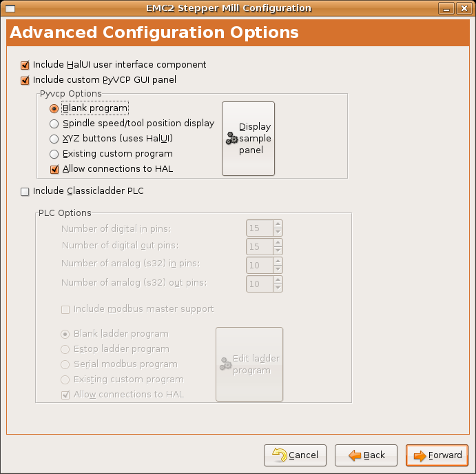
The StepConf Wizard will create several files and place them in the
linuxcnc/configs/pyvcp_xyz directory. If you left the create link checked
you will have a link to those files on your desktop.
3.1. Create the Widgets
Open up the custompanel.xml file by right clicking on it and selecting open with text editor. Between the <pyvcp></pyvcp> tags we will add the widgets for our panel.
Look in the PyVCP Widgets Reference section of the manual for more detailed information on each widget documentation des widgets.
In your custompanel.xml file we will add the description of the widgets.
<pyvcp>
<labelframe text="Jog Buttons">
<font>("Helvetica",16)</font>
<!-- the X jog buttons -->
<hbox>
<relief>RAISED</relief>
<bd>3</bd>
<button>
<font>("Helvetica",20)</font>
<width>3</width>
<halpin>"x-plus"</halpin>
<text>"X+"</text>
</button>
<button>
<font>("Helvetica",20)</font>
<width>3</width>
<halpin>"x-minus"</halpin>
<text>"X-"</text>
</button>
</hbox>
<!-- the Y jog buttons -->
<hbox>
<relief>RAISED</relief>
<bd>3</bd>
<button>
<font>("Helvetica",20)</font>
<width>3</width>
<halpin>"y-plus"</halpin>
<text>"Y+"</text>
</button>
<button>
<font>("Helvetica",20)</font>
<width>3</width>
<halpin>"y-minus"</halpin>
<text>"Y-"</text>
</button>
</hbox>
<!-- the Z jog buttons -->
<hbox>
<relief>RAISED</relief>
<bd>3</bd>
<button>
<font>("Helvetica",20)</font>
<width>3</width>
<halpin>"z-plus"</halpin>
<text>"Z+"</text>
</button>
<button>
<font>("Helvetica",20)</font>
<width>3</width>
<halpin>"z-minus"</halpin>
<text>"Z-"</text>
</button>
</hbox>
<!-- the jog speed slider -->
<vbox>
<relief>RAISED</relief>
<bd>3</bd>
<label>
<text>"Jog Speed"</text>
<font>("Helvetica",16)</font>
</label>
<scale>
<font>("Helvetica",14)</font>
<halpin>"jog-speed"</halpin>
<resolution>1</resolution>
<orient>HORIZONTAL</orient>
<min_>0</min_>
<max_>80</max_>
</scale>
</vbox>
</labelframe>
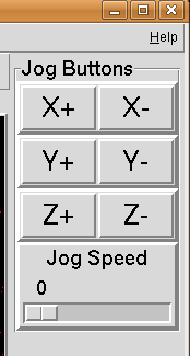
</pyvcp>After adding the above you now will have a PyVCP panel that looks like the following attached to the right side of AXIS. It looks nice but it does not do anything until you connect the buttons to halui. If you get an error when you try and run scroll down to the bottom of the pop up window and usually the error is a spelling or syntax error and it will be there.
3.2. Make Connections
To make the connections needed open up your custom_postgui.hal file and add the following.
# connect the X PyVCP buttons
net my-jogxminus halui.axis.x.minus <= pyvcp.x-minus
net my-jogxplus halui.axis.x.plus <= pyvcp.x-plus

# connect the Y PyVCP buttons
net my-jogyminus halui.axis.y.minus <= pyvcp.y-minus
net my-jogyplus halui.axis.y.plus <= pyvcp.y-plus

# connect the Z PyVCP buttons
net my-jogzminus halui.axis.z.minus <= pyvcp.z-minus
net my-jogzplus halui.axis.z.plus <= pyvcp.z-plus

# connect the PyVCP jog speed slider
net my-jogspeed halui.axis.jog-speed <= pyvcp.jog-speed-f
After resetting the E-Stop and putting it into jog mode and moving the jog speed slider in the PyVCP panel to a value greater than zero the PyVCP jog buttons should work. You can not jog when running a G-code file or while paused or while the MDI tab is selected.
4. Port Tester
This example shows you how to make a simple parallel port tester using PyVCP and HAL.
First create the ptest.xml file with the following code to create the panel description.
<!-- Test panel for the parallel port cfg for out -->
<pyvcp>
<hbox>
<relief>RIDGE</relief>
<bd>2</bd>
<button>
<halpin>"btn01"</halpin>
<text>"Pin 01"</text>
</button>
<led>
<halpin>"led-01"</halpin>
<size>25</size>
<on_color>"green"</on_color>
<off_color>"red"</off_color>
</led>
</hbox>
<hbox>
<relief>RIDGE</relief>
<bd>2</bd>
<button>
<halpin>"btn02"</halpin>
<text>"Pin 02"</text>
</button>
<led>
<halpin>"led-02"</halpin>
<size>25</size>
<on_color>"green"</on_color>
<off_color>"red"</off_color>
</led>
</hbox>
<hbox>
<relief>RIDGE</relief>
<bd>2</bd>
<label>
<text>"Pin 10"</text>
<font>("Helvetica",14)</font>
</label>
<led>
<halpin>"led-10"</halpin>
<size>25</size>
<on_color>"green"</on_color>
<off_color>"red"</off_color>
</led>
</hbox>
<hbox>
<relief>RIDGE</relief>
<bd>2</bd>
<label>
<text>"Pin 11"</text>
<font>("Helvetica",14)</font>
</label>
<led>
<halpin>"led-11"</halpin>
<size>25</size>
<on_color>"green"</on_color>
<off_color>"red"</off_color>
</led>
</hbox>
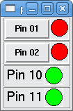
</pyvcp>This will create the following floating panel which contains a couple of in pins and a couple of out pins.
To run the HAL commands that we need to get everything up and running we put the following in our ptest.hal file.
loadrt hal_parport cfg="0x378 out"
loadusr -Wn ptest pyvcp -c ptest ptest.xml
loadrt threads name1=porttest period1=1000000
addf parport.0.read porttest
addf parport.0.write porttest
net pin01 ptest.btn01 parport.0.pin-01-out ptest.led-01
net pin02 ptest.btn02 parport.0.pin-02-out ptest.led-02
net pin10 parport.0.pin-10-in ptest.led-10
net pin11 parport.0.pin-11-in ptest.led-11
start
To run the HAL file we use the following command from a terminal window.
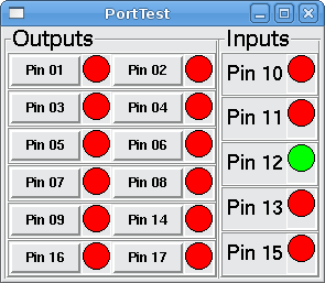
~$ halrun -I -f ptest.halThe following figure shows what a complete panel might look like.
To add the rest of the parallel port pins just modify the XML and HAL files.
To show the pins after running the HAL script use the following command at the halcmd prompt:
halcmd: show pin
Component Pins:
Owner Type  Dir Value  Name
    2 bit   IN  FALSE  parport.0.pin-01-out <== pin01
    2 bit   IN  FALSE  parport.0.pin-02-out <== pin02
    2 bit   IN  FALSE  parport.0.pin-03-out
    2 bit   IN  FALSE  parport.0.pin-04-out
    2 bit   IN  FALSE  parport.0.pin-05-out
    2 bit   IN  FALSE  parport.0.pin-06-out
    2 bit   IN  FALSE  parport.0.pin-07-out
    2 bit   IN  FALSE  parport.0.pin-08-out
    2 bit   IN  FALSE  parport.0.pin-09-out
    2 bit   OUT TRUE   parport.0.pin-10-in ==> pin10
    2 bit   OUT FALSE  parport.0.pin-10-in-not
    2 bit   OUT TRUE   parport.0.pin-11-in ==> pin11
    2 bit   OUT FALSE  parport.0.pin-11-in-not
    2 bit   OUT TRUE   parport.0.pin-12-in
    2 bit   OUT FALSE  parport.0.pin-12-in-not
    2 bit   OUT TRUE   parport.0.pin-13-in
    2 bit   OUT FALSE  parport.0.pin-13-in-not
    2 bit   IN  FALSE  parport.0.pin-14-out
    2 bit   OUT TRUE   parport.0.pin-15-in
    2 bit   OUT FALSE  parport.0.pin-15-in-not
    2 bit   IN  FALSE  parport.0.pin-16-out
    2 bit   IN  FALSE  parport.0.pin-17-out
    4 bit   OUT FALSE  ptest.btn01 ==> pin01
    4 bit   OUT FALSE  ptest.btn02 ==> pin02
    4 bit   IN  FALSE  ptest.led-01 <== pin01
    4 bit   IN  FALSE  ptest.led-02 <== pin02
    4 bit   IN  TRUE   ptest.led-10 <== pin10
    4 bit   IN  TRUE   ptest.led-11 <== pin11
This will show you what pins are IN and what pins are OUT as well as any connections.
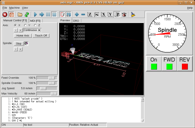
5. GS2 RPM Meter
The following example uses the Automation Direct GS2 VDF driver and displays the RPM and other info in a PyVCP panel. This example is based on the GS2 example in the Hardware Examples section this manual.
5.1. The Panel
To create the panel we add the following to the XML file.
<pyvcp>

  <!-- the RPM meter -->
  <hbox>
    <relief>RAISED</relief>
    <bd>3</bd>
    <meter>
      <halpin>"spindle_rpm"</halpin>
      <text>"Spindle"</text>
      <subtext>"RPM"</subtext>
      <size>200</size>
      <min_>0</min_>
      <max_>3000</max_>
      <majorscale>500</majorscale>
      <minorscale>100</minorscale>
      <region1>0,10,"yellow"</region1>
    </meter>
  </hbox>

  <!-- the On Led -->
  <hbox>
  <relief>RAISED</relief>
  <bd>3</bd>
  <vbox>
  <relief>RAISED</relief>
  <bd>2</bd>
  <label>
  <text>"On"</text>
  <font>("Helvetica",18)</font>
  </label>
  <width>5</width>
   <hbox>
  <label width="2"/> <!-- used to center the led -->
  <rectled>
  <halpin>"on-led"</halpin>
  <height>"30"</height>
  <width>"30"</width>
  <on_color>"green"</on_color>
  <off_color>"red"</off_color>
  </rectled>
  </hbox>
  </vbox>

  <!-- the FWD Led -->
  <vbox>
    <relief>RAISED</relief>
    <bd>2</bd>
    <label>
      <text>"FWD"</text>
      <font>("Helvetica",18)</font>
      <width>5</width>
    </label>
   <label width="2"/>
    <rectled>
      <halpin>"fwd-led"</halpin>
      <height>"30"</height>
      <width>"30"</width>
      <on_color>"green"</on_color>
      <off_color>"red"</off_color>
    </rectled>
  </vbox>

  <!-- the REV Led -->
  <vbox>
  <relief>RAISED</relief>
  <bd>2</bd>
    <label>
      <text>"REV"</text>
      <font>("Helvetica",18)</font>
       <width>5</width>
    </label>
    <label width="2"/>
    <rectled>
      <halpin>"rev-led"</halpin>
      <height>"30"</height>
      <width>"30"</width>
      <on_color>"red"</on_color>
      <off_color>"green"</off_color>
    </rectled>
  </vbox>
  </hbox>
</pyvcp>
The above gives us a PyVCP panel that looks like the following.
5.2. The Connections
To make it work we add the following code to the custom_postgui.hal file.
# display the rpm based on freq * rpm per hz
loadrt mult2
addf mult2.0 servo-thread
setp mult2.0.in1 28.75
net cypher_speed mult2.0.in0 <= spindle-vfd.frequency-out
net speed_out pyvcp.spindle_rpm <= mult2.0.out

# run led
net gs2-run => pyvcp.on-led

# fwd led
net gs2-fwd => pyvcp.fwd-led

# rev led
net running-rev spindle-vfd.spindle-rev => pyvcp.rev-led
Some of the lines might need some explanations. The fwd led line uses the signal created in the custom.hal file whereas the rev led needs to use the spindle-rev bit. You can’t link the spindle-fwd bit twice so you use the signal that it was linked to.
6. Rapid to Home Button
This example creates a button on the PyVCP side panel when pressed will send all the axis back to the home position. This example assumes you don’t have a PyVCP panel.
In your configuration directory create the XML file. In this example it’s named rth.xml. In the rth.xml file add the following code to create the button.
<pyvcp>
<!-- rapid to home button example -->
<button>
<halpin>"rth-button"</halpin>
<text>"Rapid to Home"</text>
</button>
</pyvcp>
Open your INI file with a text editor and in the [DISPLAY] section add the following line. This is what loads the PyVCP panel.
PYVCP = rth.xml
If you don’t have a [HALUI] section in the INI file create it and add the following MDI command.
MDI_COMMAND = G53 G0 X0 Y0 Z0
In the [HAL] section if you don’t have a post gui file add the following and create a file called postgui.hal.
POSTGUI_HALFILE = postgui.hal
In the postgui.hal file add the following code to link the PyVCP button to the MDI command.
net rth halui.mdi-command-00 <= pyvcp.rth-button
|
Note
|
Information about the net command |