 Figure: Diagrammes blocs de Parport
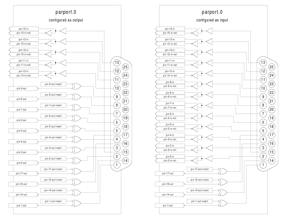
Parport est un pilote pour le port parallèle traditionnel des PC. Le port dispose d'un total de 17 broches physiques. Le port parallèle originel a divisé ces broches en trois groupes: données, contrôles et états. Le groupe “données” consiste en 8 broches de sortie, le groupe “contrôles” consiste en 4 broches et le groupe “états” consiste en 5 broches d'entrée.
Au début des années 1990, le port parallèle bidirectionnel est arrivé, ce qui a permis à l'utilisateur d'ajuster le groupe des données comme étant des sorties ou comme étant des entrées. Le pilote de HAL supporte le port bidirectionnel et permet à l'utilisateur de configurer le groupe des données en entrées ou en sorties. Si il est configuré en sorties, un port fournit un total de 12 sorties et 5 entrées. Si il est configuré en entrées, il fournit 4 sorties et 13 entrées.
Dans certains ports parallèles, les broches du groupe contrôle sont des collecteurs ouverts, ils peuvent aussi être mis à l'état bas par une porte extérieure. Sur une carte avec les broches de contrôle en collecteurs ouverts, le mode “x” de HAL permet un usage plus flexible avec 8 sorties dédiées, 5 entrées dédiées et 4 broches en collecteurs ouverts. Dans d'autres ports parallèles, les broches du groupe contrôles sont en push-pull et ne peuvent pas être utilisées comme des entrées.1
Aucune autre combinaison n'est supportée. Un port ne peut plus être modifié pour passer d'entrées en sorties dès que le pilote est installé. La figure [.] montre deux diagrammes, un montre le pilote quand le groupe de données est configuré en sorties et le second le montre configuré en entrées.
Le pilote parport peut contrôler au maximum 8 ports (définis par MAX_PORTS dans le fichier hal_parport.c). Les ports sont numérotés à partir de zéro.
loadrt hal_parport cfg="<config-string>"
La chaine config-string représente l'adresse hexadécimale du port, suivie optionnellement par une direction, le tout répété pour chaque port. Les directions sont “in”, “out”, ou “x”, elles déterminent la direction des broches physiques 2 à 9 et s'il y a lieu de créer des pins d'entrée de HAL pour les broches de contrôle physiques. Si la direction n'est pas précisée, le groupe données sera par défault en sortie. Par exemple:
loadrt hal_parport cfg="0x278 0x378 in 0x20A0 out"
Cet exemple installe les pilotes pour un port 0x0278, avec les broches 2 à 9 en sorties (par défaut, puisque ni “ in ”, ni “out” n'est spécifié), un port 0x0378, avec les broches 2 à 9 en entrées et un port 0x20A0, avec les broches 2 à 9 explicitement spécifiées en sorties. Notez que vous devez connaître l'adresse de base des ports parallèles pour configurer correctement les pilotes. Pour les ports sur bus ISA, ce n'est généralement pas un problème, étant donné que les ports sont presque toujours à une adresse “bien connue”, comme 0x278 ou 0x378 qui sont typiquement configurées dans le BIOS. Les adresses des cartes sur bus PCI sont habituellement trouvées avec “lspci -v” dans une ligne “I/O ports”, ou dans un message du kernel après l'exécution de “sudo modprobe -a parport_pc”. Il n'y a pas d'adresse par défaut, si <config-string> ne contient pas au moins une adresse, un message d'erreur s'affichera.
Pour chaque pin, <portnum> est le numéro du port et <pinnum> est le numéro de la broche physique du connecteur DB-25.
Pour chaque broche de sortie physique, le pilote crée une simple pin de HAL, par exemple parport.0.pin-14-out. Les pins 2 jusqu'à 9 font partie du groupe données, elles sont des pins de sortie si le port est défini comme un port de sorties (par défaut en sortie). Les broches 1, 14, 16 et 17 sont des sorties dans tous les modes. Ces pins de HAL contrôlent l'état des pins physiques correspondantes.
Pour chaque pin d'entrée physique, le pilote crée deux pins de HAL, par exemple parport.0.pin-12-in et parport.0.pin-12-in-not. Les pins 10, 11, 12, 13 et 15 sont toujours des sorties. Les pins 2 jusqu'à 9 sont des pins d'entrée seulement si le port est défini comme un port d'entrées. Une pin de HAL -in est VRAIE si la pin physique est haute et FAUSSE si la pin physique est basse. Une pin de HAL -in-not est inversée, elle est FAUSSE si la pin physique est haute. En connectant un signal à l'une ou à l'autre, l'utilisateur peut décider de la logique de l'entrée. En mode “x”, les pins 1, 14, 16 et 17 sont également des pins d'entrée.
Le paramètre -invert détermine si une pin de sortie est active haute ou active basse. Si -invert est FAUX, mettre la pin HAL -out VRAIE placera la pin physique à l'état haut et mettre la pin HAL FAUSSE placera la pin physique à l'état bas. Si -invert est VRAI, mettre la pin HAL -out VRAIE va mettre la pin physique à l'état bas.
Si -reset est VRAI, la fonction de réinitialisation va passer la pin à la valeur de -out-invert. Ceci peut être utilisé en conjonction avec “stepgen doublefreq” pour produire un pas par période.
Les différentes fonctions sont prévues pour les situations où un port doit être mis à jour dans un thread très rapide, mais d'autres ports peuvent être mis à jour dans un thread plus lent pour gagner du temps CPU. Ce n'est probablement pas une bonne idée d'utiliser en même temps, les fonctions -all et une fonction individuelle.
Si le chargement du module le message suivant:
insmod: error inserting '/home/jepler/emc2/rtlib/hal_parport.ko':
-1 Device or resource busy
s'assurer que le noyau du kernel standard, parport_pc, n'est pas chargé2 et qu'aucun périphérique dans le système ne revendique les ports concernés.
SI le module est chargé mais ne semble pas fonctionner, l'adresse du port est incorrecte ou le module probe_parport est requis.
Dans les PC récents, le port parallèle peut exiger une configuration plug and play (PNP) avant d'être utilisable. Le module probe_parport effectue la configuration de tous les ports PNP présents et devrait être chargé avant hal_parport. Sur les machines sans ports PNP, il peut être chargé mais n'a aucun effet.
loadrt probe_parport
loadrt hal_parport ...
Si le kernel Linux affiche un message similaire à:
parport: PnPBIOS parport detected.
Quand le module parport_pc est chargé, avec la commande: sudo modprobe -a parport_pc; sudo rmmod parport_pc, l'utilisation de ce module sera probablement nécessaire.
.
Les modules commerciaux ci-dessous pouront êtres traduits en français sur demande.
The commercial modules below could be translated into French on request.
.
The Axiom Measurement & Control AX5214H is a 48 channel digital I/O board. It plugs into an ISA bus, and resembles a pair of 8255 chips.3
loadrt hal_ax5214h cfg="<config-string>"
The config string consists of a hex port address, followed by an 8 character string of “I” and “O” which sets groups of pins as inputs and outputs. The first two character set the direction of the first two 8 bit blocks of pins (0-7 and 8-15). The next two set blocks of 4 pins (16-19 and 20-23). The pattern then repeats, two more blocks of 8 bits (24-31 and 32-39) and two blocks of 4 bits (40-43 and 44-47). If more than one board is installed, the data for the second board follows the first. As an example, the string "0x220 IIIOIIOO 0x300 OIOOIOIO" installs drivers for two boards. The first board is at address 0x220, and has 36 inputs (0-19 and 24-39) and 12 outputs (20-23 and 40-47). The second board is at address 0x300, and has 20 inputs (8-15, 24-31, and 40-43) and 28 outputs (0-7. 16-23, 32-39, and 44-47). Up to 8 boards may be used in one system.
For each pin, <boardnum> is the board number (starts at zero), and <pinnum> is the I/O channel number (0 to 47).
Note that the driver assumes active LOW signals. This is so that modules such as OPTO-22 will work correctly (TRUE means output ON, or input energized). If the signals are being used directly without buffering or isolation the inversion needs to be accounted for. The in- HAL pin is TRUE if the physical pin is low (OPTO-22 module energized), and FALSE if the physical pin is high (OPTO-22 module off). The in-<pinnum>-not HAL pin is inverted -- it is FALSE if the physical pin is low (OPTO-22 module energized). By connecting a signal to one or the other, the user can determine the state of the input.
The -invert parameter determines whether an output pin is active high or active low. If -invert is FALSE, setting the HAL out- pin TRUE drives the physical pin low, turning ON an attached OPTO-22 module, and FALSE drives it high, turning OFF the OPTO-22 module. If -invert is TRUE, then setting the HAL out- pin TRUE will drive the physical pin high and turn the module OFF.
The Servo-To-Go is one of the first PC motion control cards4 supported by EMC. It is an ISA card and it exists in different flavours (all supported by this driver). The board includes up to 8 channels of quadrature encoder input, 8 channels of analog input and output, 32 bits digital I/O, an interval timer with interrupt and a watchdog.
loadrt hal_stg [base=<address>] [num_chan=<nr>] [dio="<dio-string>"] [model=<model>]
The base address field is optional; if it's not provided the driver attempts to autodetect the board. The num_chan field is used to specify the number of channels available on the card, if not used the 8 axis version is assumed. The digital inputs/outputs configuration is determined by a config string passed to insmod when loading the module. The format consists of a four character string that sets the direction of each group of pins. Each character of the direction string is either "I" or "O". The first character sets the direction of port A (Port A - DIO.0-7), the next sets port B (Port B - DIO.8-15), the next sets port C (Port C - DIO.16-23), and the fourth sets port D (Port D - DIO.24-31). The model field can be used in case the driver doesn't autodetect the right card version5. For example:
loadrt hal_stg base=0x300 num_chan=4 dio="IOIO"
This example installs the stg driver for a card found at the base address of 0x300, 4 channels of encoder feedback, DAC's and ADC's, along with 32 bits of I/O configured like this: the first 8 (Port A) configured as Input, the next 8 (Port B) configured as Output, the next 8 (Port C) configured as Input, and the last 8 (Port D) configured as Output
loadrt hal_stg
This example installs the driver and attempts to autodetect the board address and board model, it installs 8 axes by default along with a standard I/O setup: Port A & B configured as Input, Port C & D configured as Output.
For each pin, <channel> is the axis number, and <pinnum> is the logic pin number of the STG6.
The in- HAL pin is TRUE if the physical pin is high, and FALSE if the physical pin is low. The in-<pinnum>-not HAL pin is inverted -- it is FALSE if the physical pin is high. By connecting a signal to one or the other, the user can determine the state of the input.
The -invert parameter determines whether an output pin is active high or active low. If -invert is FALSE, setting the HAL out- pin TRUE drives the physical pin high, and FALSE drives it low. If -invert is TRUE, then setting the HAL out- pin TRUE will drive the physical pin low.
The Mesa Electronics m5i20 card consists of an FPGA that can be loaded with a wide variety of configurations, and has 72 pins that leave the PC. The assignment of the pins depends on the FPGA configuration. Currently there is a HAL driver for the “4 axis host based motion control” configuration, and this FPGA configurations is also provided with EMC2. It provides 8 encoder counters, 4 PWM outputs (normally used as DACs) and up to 48 digital I/O channels, 32 inputs and 16 outputs.7
Installing:
loadrt hal_m5i20 [loadFpga=1|0] [dacRate=<rate>]
If loadFpga is 1 (the default) the driver will load the FPGA configuration on startup. If it is 0, the driver assumes the configuration is already loaded. dacRate sets the carrier frequency for the PWM outputs, in Hz. The default is 32000, for 32KHz PWM. Valid values are from 1 to 32226. The driver prints some useful debugging message to the kernel log, which can be viewed with dmesg.
Up to 4 boards may be used in one system.
In the following pins, parameters, and functions, <board> is the board ID. According to the naming conventions the first board should always have an ID of zero, however this driver uses the PCI board ID, so it may be non-zero even if there is only one board.
| Bit # | Value | Meaning |
| 0 | 1 | Watchdog is enabled |
| 1 | 2 | Watchdog is automatically reset by DAC writes (the HAL dac-write function) |
The Hostmot-4 FPGA configuration has the following pinout. There are three 50-pin ribbon cable connectors on the card: P2, P3, and P4. There are also 8 status LEDs.
| m5i20 card connector P2 | Function/HAL-pin |
| 1 | enc-01 A input |
| 3 | enc-01 B input |
| 5 | enc-00 A input |
| 7 | enc-00 B input |
| 9 | enc-01 index input |
| 11 | enc-00 index input |
| 13 | dac-01 output |
| 15 | dac-00 output |
| 17 | DIR output for dac-01 |
| 19 | DIR output for dac-00 |
| 21 | dac-01-enable output |
| 23 | dac-00-enable output |
| 25 | enc-03 B input |
| 27 | enc-03 A input |
| 29 | enc-02 B input |
| 31 | enc-02 A input |
| 33 | enc-03 index input |
| 35 | enc-02 index input |
| 37 | dac-03 output |
| 39 | dac-02 output |
| 41 | DIR output for dac-03 |
| 43 | DIR output for dac-02 |
| 45 | dac-03-enable output |
| 47 | dac-02-enable output |
| 49 | Power +5 V (or +3.3V ?) |
| all even pins | Ground |
Encoder counters 4 - 7 work simultaneously with in-00 to in-11.
If you are using in-00 to in-11 as general purpose IO then reading enc-<4-7> will produce some random junk number.
| m5i20 card connector P3 | Function/HAL-pin | Secondary Function/HAL-pin |
| 1 | in-00 | enc-04 A input |
| 3 | in-01 | enc-04 B input |
| 5 | in-02 | enc-04 index input |
| 7 | in-03 | enc-05 A input |
| 9 | in-04 | enc-05 B input |
| 11 | in-05 | enc-05 index input |
| 13 | in-06 | enc-06 A input |
| 15 | in-07 | enc-06 B input |
| 17 | in-08 | enc-06 index input |
| 19 | in-09 | enc-07 A input |
| 21 | in-10 | enc-07 B input |
| 23 | in-11 | enc-07 index input |
| 25 | in-12 | |
| 27 | in-13 | |
| 29 | in-14 | |
| 31 | in-15 | |
| 33 | out-00 | |
| 35 | out-01 | |
| 37 | out-02 | |
| 39 | out-03 | |
| 41 | out-04 | |
| 43 | out-05 | |
| 45 | out-06 | |
| 47 | out-07 | |
| 49 | Power +5 V (or +3.3V ?) | |
| all even pins | Ground |
The index mask masks the index input of the encoder so that the encoder index can be combined with a mechanical switch or opto detector to clear or latch the encoder counter only when the mask input bit is in proper state (selected by mask polarity bit) and encoder index occurs. This is useful for homing. The behaviour of these pins is controlled by the Counter Control Register (CCR), however there is currently no function in the driver to change the CCR. See REGMAP49 for a description of the CCR.
| m5i20 card connector P4 | Function/HAL-pin | Secondary Function/HAL-pin |
| 1 | in-16 | enc-00 index mask |
| 3 | in-17 | enc-01 index mask |
| 5 | in-18 | enc-02 index mask |
| 7 | in-19 | enc-03 index mask |
| 9 | in-20 | |
| 11 | in-21 | |
| 13 | in-22 | |
| 15 | in-23 | |
| 17 | in-24 | enc-04 index mask |
| 19 | in-25 | enc-05 index mask |
| 21 | in-26 | enc-06 index mask |
| 23 | in-27 | enc-07 index mask |
| 25 | in-28 | |
| 27 | in-29 | |
| 29 | in-30 | |
| 31 | in-31 | |
| 33 | out-08 | |
| 35 | out-09 | |
| 37 | out-10 | |
| 39 | out-11 | |
| 41 | out-12 | |
| 43 | out-13 | |
| 45 | out-14 | |
| 47 | out-15 | |
| 49 | Power +5 V (or +3.3V ?) | |
| all even pins | Ground |
The status LEDs will monitor one motion channel set by the m5i20.<board>.led-view parameter. A call to m5i20.<board>.misc-update is required to update the viewed channel.
| LED name | Output |
| LED0 | IRQLatch ? |
| LED1 | enc-<channel> A |
| LED2 | enc-<channel> B |
| LED3 | enc-<channel> index |
| LED4 | dac-<channel> DIR |
| LED5 | dac-<channel> |
| LED6 | dac-<channel>-enable |
| LED7 | watchdog timeout ? |
The Vital Systems Motenc-100 and Motenc-LITE are 8- and 4-channel servo control boards. The Motenc-100 provides 8 quadrature encoder counters, 8 analog inputs, 8 analog outputs, 64 (68?) digital inputs, and 32 digital outputs. The Motenc-LITE has only 4 encoder counters, 32 digital inputs and 16 digital outputs, but it still has 8 analog inputs and 8 analog outputs. The driver automatically identifies the installed board and exports the appropriate HAL objects.10
Installing:
loadrt hal_motenc
During loading (or attempted loading) the driver prints some usefull debugging message to the kernel log, which can be viewed with dmesg.
Up to 4 boards may be used in one system.
In the following pins, parameters, and functions, <board> is the board ID. According to the naming conventions the first board should always have an ID of zero. However this driver sets the ID based on a pair of jumpers on the baord, so it may be non-zero even if there is only one board.
| Bit # | Value | Meaning |
| 0 | 1 | Timeout is 16ms if set, 8ms if unset |
| 2 | 4 | Watchdog is enabled |
| 4 | 16 | Watchdog is automatically reset by DAC writes (the HAL dac-write function) |
Pico Systems has a family of boards for doing servo, stepper, and pwm control. The boards connect to the PC through a parallel port working in EPP mode. Although most users connect one board to a parallel port, in theory any mix of up to 8 or 16 boards can be used on a single parport. One driver serves all types of boards. The final mix of I/O depends on the connected board(s). The driver doesn't distinguish between boards, it simply numbers I/O channels (encoders, etc) starting from 0 on the first card.
Installing:
loadrt hal_ppmc port_addr=<addr1>[,<addr2>[,<addr3>...]]
The port_addr parameter tells the driver what parallel port(s) to check. By default, <addr1> is 0x0378, and <addr2> and following are not used. The driver searches the entire address space of the enhanced parallel port(s) at port_addr, looking for any board(s) in the PPMC family. It then exports HAL pins for whatever it finds. During loading (or attempted loading) the driver prints some usefull debugging message to the kernel log, which can be viewed with dmesg.
Up to 3 parport busses may be used, and each bus may have up to 8 devices on it.
In the following pins, parameters, and functions, <board> is the board ID. According to the naming conventions the first board should always have an ID of zero. However this driver sets the ID based on a pair of jumpers on the baord, so it may be non-zero even if there is only one board.
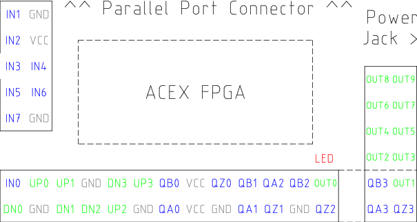
The Pluto-P is an inexpensive ($60) FPGA board featuring the ACEX1K chip from Altera.
The src/hal/drivers/pluto_servo_firmware/ and src/hal/drivers/pluto_step_firmware/ subdirectories contain the Verilog source code plus additional files used by Quartus for the FPGA firmwares. Altera's Quartus II software is required to rebuild the FPGA firmware. To rebuild the firmware from the .hdl and other source files, open the .qpf file and press CTRL-L. Then, recompile emc2.
Like the HAL hardware driver, the FPGA firmware is licensed under the terms of the GNU General Public License.
The gratis version of Quartus II runs only on Microsoft Windows, although there is apparently a paid version that runs on Linux.
The Pluto-P board may be ordered from http://www.knjn.com/ShopBoards_Parallel.html (US based, international shipping is available). Some additional information about it is available from http://www.fpga4fun.com/board_pluto-P.html and from the developer's blog.
The pluto_servo system is suitable for control of a 4-axis CNC mill with servo motors, a 3-axis mill with PWM spindle control, a lathe with spindle encoder, etc. The large number of inputs allows a full set of limit switches.
This driver features:
| Primary function | Alternate Function | Behavior if both functions used |
| UP0 | PWM0 | When pwm-0-pwmdir is TRUE, this pin is the PWM output |
| OUT10 | XOR'd with UP0 or PWM0 | |
| UP1 | PWM1 | When pwm-1-pwmdir is TRUE, this pin is the PWM output |
| OUT12 | XOR'd with UP1 or PWM1 | |
| UP2 | PWM2 | When pwm-2-pwmdir is TRUE, this pin is the PWM output |
| OUT14 | XOR'd with UP2 or PWM2 | |
| UP3 | PWM3 | When pwm-3-pwmdir is TRUE, this pin is the PWM output |
| OUT16 | XOR'd with UP3 or PWM3 | |
| DN0 | DIR0 | When pwm-0-pwmdir is TRUE, this pin is the DIR output |
| OUT11 | XOR'd with DN0 or DIR0 | |
| DN1 | DIR1 | When pwm-1-pwmdir is TRUE, this pin is the DIR output |
| OUT13 | XOR'd with DN1 or DIR1 | |
| DN2 | DIR2 | When pwm-2-pwmdir is TRUE, this pin is the DIR output |
| OUT15 | XOR'd with DN2 or DIR2 | |
| DN3 | DIR3 | When pwm-3-pwmdir is TRUE, this pin is the DIR output |
| OUT17 | XOR'd with DN3 or DIR3 | |
| QZ0 | IN8 | Read same value |
| QZ1 | IN9 | Read same value |
| QZ2 | IN10 | Read same value |
| QZ3 | IN11 | Read same value |
| QA0 | IN12 | Read same value |
| QA1 | IN13 | Read same value |
| QA2 | IN14 | Read same value |
| QA3 | IN15 | Read same value |
| QB0 | IN16 | Read same value |
| QB1 | IN17 | Read same value |
| QB2 | IN18 | Read same value |
| QB3 | IN19 | Read same value |
A list of all 'loadrt' arguments, HAL function names, pin names and parameter names is in the manual page, pluto_servo.9.
A schematic for a 2A, 2-axis PWM servo amplifier board is available (http://emergent.unpy.net/projects/01148303608). The L298 H-Bridge (L298 H-bridge) is inexpensive and can easily be used for motors up to 4A (one motor per L298) or up to 2A (two motors per L298) with the supply voltage up to 46V. However, the L298 does not have built-in current limiting, a problem for motors with high stall currents. For higher currents and voltages, some users have reported success with International Rectifier's integrated high-side/low-side drivers. (http://www.cnczone.com/forums/showthread.php?t=25929)
Pluto-step is suitable for control of a 3- or 4-axis CNC mill with stepper motors. The large number of inputs allows for a full set of limit switches.
The board features:
While the “extended main connector” has a superset of signals usually found on a Step & Direction DB25 connector--4 step generators, 9 inputs, and 6 general-purpose outputs--the layout on this header is different than the layout of a standard 26-pin ribbon cable to DB25 connector.
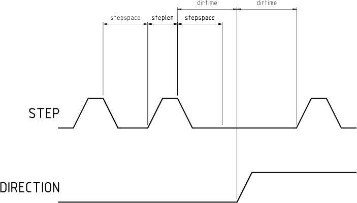
The firmware and driver enforce step length, space, and direction change times. Timings are rounded up to the next multiple of 1.6μs, with a maximum of 49.6μs. The timings are the same as for the software stepgen component, except that “dirhold” and “dirsetup” have been merged into a single parameter “dirtime” which should be the maximum of the two, and that the same step timings are always applied to all channels.
A list of all 'loadrt' arguments, HAL function names, pin names and parameter names is in the manual page, pluto_step.9.
1 HAL ne peut pas déterminer automatiquement si les broches en mode bidirectionnel “x” sont effectivement en collecteurs ouverts (OC). Si elles n'y sont pas, elles ne peuvent pas être utilisées comme des entrées. Essayer de les passer à l'état BAS par une source extérieure peut détériorer le matériel. Pour déterminer si votre port a des broches de contrôle en “collecteur ouvert”, charger hal_parport en mode “x”, positionner les broches de contrôle à une valeur HAUTE. HAL doit lire des pins à l'état VRAI. Ensuite, insérer une résistance de 470Ω entre une des broches de contrôle et GND du port parallèle. Si la tension de cette broche de contrôle est maintenant proche de 0V et que HAL la lit comme une pin FAUSSE, alors vous avez un port OC. Si la tension résultante est loin de 0V ou que HAL ne la lit pas comme étant FAUSSE, votre port ne ne peut pas être utilisé en mode “x”. Le matériel extérieur qui pilote les broches de contrôle devrait également utiliser des portes en collecteur ouvert (ex: 74LS05...). Généralement, une pin de HAL -out devrait être VRAIE quand la pin physique est utilisée comme une entrée. Sur certaines machines, les paramètres du BIOS peuvent affecter la possibilité d'utiliser le mode “x”. Le mode “SPP” est le mode qui fonctionne le plus fréquemment. Retour
2 In the emc packages for Ubuntu, the file /etc/modprobe.d/emc2 generally prevents parport_pc from being automatically loaded. Retour
3 In fact it may be a pair of 8255 chips, but I'm not sure. If/when someone starts a driver for an 8255 they should look at the ax5214 code, much of the work is already done. Retour
4 a motion control card usually is a board containing devices to control one or more axes (the control devices are usually DAC's to set an analog voltage, encoder counting chips for feedback, etc.) Retour
5 hint: after starting up the driver, 'dmesg' can be consulted for messages relevant to the driver (e.g. autodetected version number and base address) Retour
6 if IIOO is defined, there are 16 input pins (in-00 .. in-15) and 16 output pins (out-00 .. out-15), and they correspond to PORTs ABCD (in-00 is PORTA.0, out-15 is PORTD.7) Retour
7 Ideally the encoders, “DACs”, and digital I/O would comply with the canonical interfaces defined earlier, but they don't. Fixing that is on the things-to-do list. Retour
8 With normal 10 bit PWM, 50% duty cycle would be 512 cycles on and 512 cycles off = ca 30 kHz with 33 MHz reference counter. With fully interleaved PWM this would be 1 cycle on, 1 cycle off for 1024 cycles (16.66 MHz if the PWM reference counter runs at 33 MHz) = much easier to filter. The 5I20 configuration interlace is somewhat between non and fully interlaced (to make it easy to filter but not have as many transistions as fully interleaved). Retour
9 emc2/src/hal/drivers/m5i20/REGMAP4E Retour
10 Ideally the encoders, DACs, ADCs, and digital I/O would comply with the canonical interfaces defined earlier, but they don't. Fixing that is on the things-to-do list. Retour
11 Index handling does _not_ comply with the canonical encoder interface, and should be changed. Retour