 Figure: Touch Off Tool Table
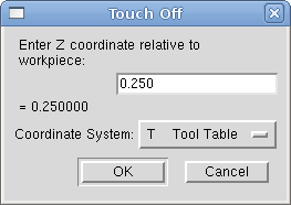
Using the Touch Off Screen in the AXIS interface you can update the tool table automatically.
Typical steps for updating the tool table:
The Tool Table will be changed with the correct Z length to make the DRO display the correct Z position and a G43 command will be issued so the new tool Z length will be in effect. Tool table touch off is only available when a tool is loaded with "TnM6".
By using "G10 L1 Pn Zx" where "n" is the tool number and "x" is the offset from the MDI window or in your program you can also set the tool table.
The "Tool Table" is a text file that contains information about each tool. The file is located in the same directory as your configuration and is called "tool.tbl". The tools might be in a tool changer or just changed manually. The file can be edited with a text editor or be updated using G10 L1. See the Lathe Specifics Section for lathe tool table example. The maximum number of entries in the tool table is 56. The maximum tool and pocket number is 99999.
| T1 | P1 | D0.125000 | Z+0.511000 | ;1/8” End Mill |
| T2 | P2 | D0.062500 | Z+0.100000 | ;1/16” End Mill |
| T99999 | P99999 | D23.75000 | Z-0.3000000 | ;You have a lot of tools |
In general new tool table line format is:
EMC supports three types of tool changers "manual", "random location" and "fixed location". Information about configuring an EMC tool changer is in the Integrators Manual.
Manual tool changer (you change the tool by hand) is treated like a fixed location tool changer and the P number is ignored. Using the manual tool changer only makes sense if you have tool holders that remain with the tool (Cat, NMTB, Kwik Switch etc.) when changed thus preserving the location of the tool to the spindle. Machines with R-8 or router collet type tool holders do not preserve the location of the tool and the manual tool changer should not be used.
Fixed location tool changers like lathe turrets the tools are in a fixed position in the tool changer. When EMC is configured for a fixed location tool changer the "P" number is ignored (but read, preserved and rewritten) by EMC, so you can use P for any bookkeeping number you want.
Random location tool changers swaps the tool in the spindle with the one in the changer. This type of tool changer the tool location will always be in a different pocket after a tool change. When a tool is changed EMC rewrites the pocket number to keep track of where the tool are. T can be any number but P must be a number that makes sense for the machine.
Cutter Radius Compensation allows the programmer to program the tool path without knowing the exact tool diameter. The only caveat is the programmer must program the lead in move to be at least as long as the largest tool radius that might be used.
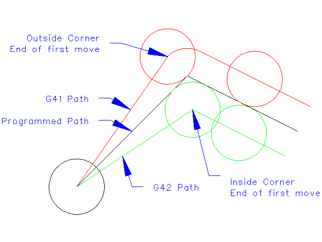
There are two possible paths the cutter can take while cutter radius compensation is on to the left or right side of a line when facing the direction of cutter motion from behind the cutter. To visualize this imagine you were standing on the part walking behind the tool as it progresses across the part. G41 is your left side of the line and G42 is the right side of the line.
The end point of each move depends on the next move. If the next move creates an outside corner the move will be to the end point of the compensated cut line. If the next move creates in an inside corner the move will stop short so to not gouge the part. The following figure shows how the compensated move will stop at different points depending on the next move.
Cutter radius compensation uses the data from the tool table to determine the offset needed. The data can be set at run time with G10 L1.
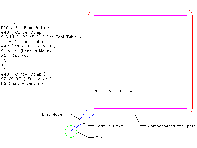
Any move that is long enough to perform the compensation will work as the entry move. The minimum lenght is the cutter radius. This can be a rapid move above the work piece. If several rapid moves are issued after a G41/42 only the last one will move the tool to the compensated position.
In the following figure you can see that the entry move is compensated to the right of the line. This puts the center of the tool to the right of X0 in this case. If you were to program a profile and the end is at X0 the resulting profile would leave a bump due to the offset of the entry move.
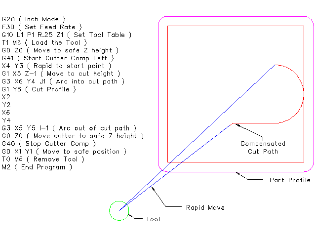
Z axis motion may take place while the contour is being followed in the XY plane. Portions of the contour may be skipped by retracting the Z axis above the part and by extending the Z-axis at the next start point.
Rapid moves may be programed while compensation is turned on.