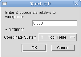
 Figure: Touch Off Tool Table
Using the Touch Off Screen in the AXIS interface you can update the tool table automatically.
Typical steps for updating the tool table:
The Tool Table will be changed with the correct Z length to make the DRO display the correct Z position and a G43 command will be issued so the new tool Z length will be in effect. Tool table touch off is only available when a tool is loaded with "TnM6".
By using "G10 L1 Pn Zx" where "n" is the tool number and "x" is the offset from the MDI window or in your program you can also set the tool table.
The "Tool Table" is a text file that contains information about each tool. The file is located in the same directory as your configuration and is called "tool.tbl". The tools might be in a tool changer or just changed manually. The file can be edited with a text editor or be updated using G10 L1.
| FMS | TLO | Diameter | Comment | |
| 1 | 1 | 2.0 | 1.0 | |
| 2 | 2 | 1.0 | 0.2 | |
| 5 | 5 | 1.5 | 0.25 | endmill |
| 10 | 10 | 2.4 | -0.3 | for testing |
Each line has five entries. The first four entries are required. The last entry (a comment) is optional. It makes reading easier if the entries are arranged in columns, as shown in the table, but the only format requirement is that there be at least one space or tab after each of the first three entries on a line and a space, tab, or newline at the end of the fourth entry. The meanings of the columns and the type of data to be put in each are as follows.
The "Pocket" column (unsigned integer) represents the pocket number or slot number of the tool carousel slot in which the tool is placed. The entries in this column must all be different.
The "FMS" column (unsigned integer) represents a code number for the tool. The user may use any code for any tool, as long as the codes are unsigned integers. This is typically the same as the pocket number.
The "TLO" column (float number) represents the tool length offset. This number will be used if tool length offsets are being used and this pocket is selected. This is normally a positive floating point number, but it may be zero or any other number if it is never to be used.
The "Diameter" column (float number) is used only if tool radius compensation is turned on using this pocket. If the programmed path during compensation is the edge of the material being cut, this should be a positive real number representing the measured diameter of the tool. If the programmed path during compensation is the path of a tool whose diameter is nominal, this should be a small number (positive, negative, or zero) representing the difference between the measured diameter of the tool and the nominal diameter. If cutter radius compensation is not used with a tool, it does not matter what number is in this column.
The "Comment" column may optionally be used to describe the tool. Any type of description is OK. This column is for the benefit of human readers only.
| FMS | ZOFFSET | XOFFSET | DIA | FRONTANGLE | BACKANGLE | ORIENTATION | Comment | |
| 1 | 1 | 0.0 | 0.0 | 0.1 | 95.0 | 155.0 | 1 | |
| 2 | 2 | 0.5 | 0.5 | 0.1 | 120 | 60 | 6 |
The Pocket, FMS, DIA and Comment columns are the same as mill format tool files.
The ZOFFSET column is the same as the TLO column of mill format tool files.
The DIA column is used by the AXIS gui display to give a visual indication of the tool diameter.
The XOFFSET column gives an offset for the X coordinate when tool length offsets are in effect.
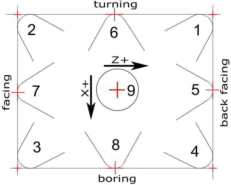
The ORIENTATION column gives the orientation of the lathe tool, as illustrated in [.]. The red cross is the controlled point. See [->].
The FRONTANGLE and BACKANGLE fields are used by some user interfaces to display a fancy representation of the lathe tool.
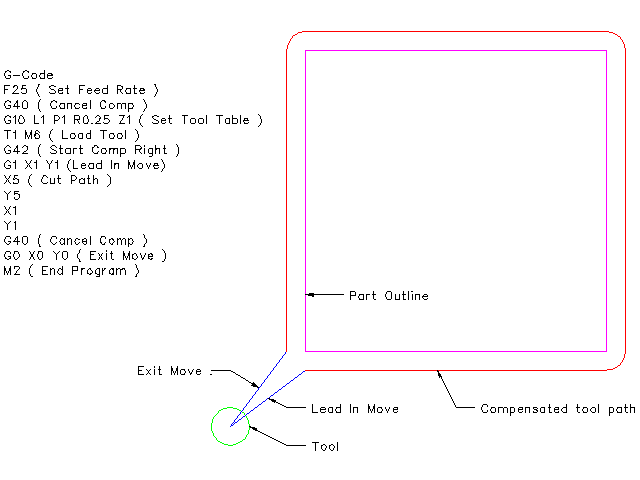
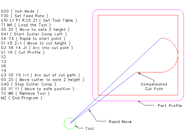
Cutter Radius Compensation allows the programmer to program the tool path without knowing the exact tool diameter. The only caveat is the programmer must program the lead in move to be at least as long as the largest tool radius that might be used.
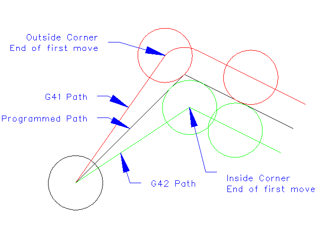
There are two possible paths the cutter can take while cutter radius compensation is on to the left or right side of a line when facing the direction of cutter motion from behind the cutter. To visualize this imagine you were standing on the part walking behind the tool as it progresses across the part. G41 is your left side of the line and G42 is the right side of the line.
The end point of each move depends on the next move. If the next move creates an outside corner the move will be to the end point of the compensated cut line. If the next move creates in an inside corner the move will stop short so to not gouge the part. The following figure shows how the compensated move will stop at different points depending on the next move.
Cutter radius compensation uses the data from the tool table to determine the offset needed. The data can be set at run time with G10 L1.
Any move that is long enough to perform the compensation will work as the entry move. The minimum lenght is the cutter radius. This can be a rapid move above the work piece. If several rapid moves are issued after a G41/42 only the last one will move the tool to the compensated position.
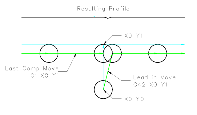
In the following figure you can see that the entry move is compensated to the right of the line. This puts the center of the tool to the right of X0 in this case. If you were to program a profile and the end is at X0 the resulting profile would leave a bump due to the offset of the entry move.
Z axis motion may take place while the contour is being followed in the XY plane. Portions of the contour may be skipped by retracting the Z axis above the part and by extending the Z-axis at the next start point.
Rapid moves may be programed while compensation is turned on.