Table of Contents
List of tables
1 Config Files
1.1 Files Used for Configuration
The EMC is configured with human readable text files. All of these files can be read and edited in any of the common text file editors available with most any Linux distribution.1 You'll need to be a bit careful when you edit these files. Some mistakes will cause the start up to fail. These files are read whenever the software starts up. Some of them are read repeatedly while the CNC is running.
Configuration files include
- INI
- The ini file overrides defaults that are compiled into the EMC code. It also provides sections that are read directly by the Hardware Abstraction Layer.
- HAL
- The hal files start up process modules and provide linkages between EMC signals and specific hardware pins.
- VAR
- The var file is a way for the interpreter to save some values from one run to the next. These values are saved from one run to another but not always saved immediately. See the Parameters section of the G Code Manual for information on what each parameter is.
- TBL
- The tbl file saves tool information. See the User Manual Tool File section for more info.
- NML
- The nml file configures the communication channels used by the EMC. It is normally setup to run all of the communication within a single computer but can be modified to communicate between several computers.
- .emcrc
- This file saves user specific information and is created to save the name of the directory when the user first selects an EMC configuration.2
Items marked (hal) are used only by the sample HAL files and are suggested as a good convention. Other items are used by EMC directly, and must always have the section and item names given.
2 INI File
2.1 The INI File Layout
A typical INI file follows a rather simple layout that includes;
- comments.
- sections,
- variables.
Each of these elements is separated on single lines. Each end of line or newline character creates a new element.
2.1.1 Comments
A comment line is started with a ; or a # mark. When the ini reader sees either of these marks at the start a line, the rest of the line is ignored by the software. Comments can be used to describe what some INI element will do.
; This is my little mill configuration file.
; I set it up on January 12, 2006
Comments can also be used to select between several values of a single variable.
# DISPLAY = tkemc
DISPLAY = axis
# DISPLAY = mini
# DISPLAY = keystick
In this list, the DISPLAY variable will be set to axis because all of the others are commented out. If someone carelessly edits a list like this and leaves two of the lines uncommented, the first one encountered will be used.
Note that inside a variable, the “#” and “;” characters do not denote comments:
INCORRECT = value # and a comment
2.1.2 Sections
Related parts of an ini file are separated into sections. A section line looks like [THIS_SECTION]. The name of the section is enclosed in brackets. The order of sections is unimportant. The following sections are used by EMC:
- [EMC] general information ([.])
- [DISPLAY] settings related to the graphical user interface ([.])
- [FILTER] settings input filter programs ([sub:[FILTER]-Section])
- [RS274NGC] settings used by the g-code interpreter ([.])
- [EMCMOT] settings used by the real time motion controller ([.])
- [HAL] specifies .hal files ([.])
- [TASK] settings used by the task controller ([.])
- [TRAJ] additional settings used by the real time motion controller ([.])
- [AXIS_0] ... [AXIS_n] individual axis variables ([.])
- [EMCIO] settings used by the I/O Controller ([.])
- [HALUI] MDI commands used by HALUI. See the HALUI chapter for more information ([->])
2.1.3 Variables
A variable line is made up of a variable name, an equals sign(=), and a value. Everything from the first non-white space character after the = up to the end of the line is passed as the value, so you can embed spaces in string symbols if you want to or need to. A variable name is often called a keyword.
The following sections detail each section of the configuration file, using sample values for the configuration lines.
Some of the variables are used by EMC, and must always use the section names and variable names shown. Other variables are used only by HAL, and the section names and variable names shown are those used in the sample configuration files.
2.1.4 Definitions
- Machine Units
- The units (of length or angle) specified in the ini file for a particular axis
2.2 Sections
2.2.1 [EMC] Section
- VERSION
- = $Revision: 1.3 $ The version number for the INI file. The value shown here looks odd because it is automatically updated when using the Revision Control System. It's a good idea to change this number each time you revise your file. If you want to edit this manually just change the number and leave the other tags alone.
- MACHINE
- = My Controller This is the name of the controller, which is printed out at the top of most graphical interfaces. You can put whatever you want here as long as you make it a single line long.
2.2.2 [DISPLAY] Section
Different user interface programs use different options, and not every option is supported by every user interface.
DISPLAY = tkemc The name of the user interface to use. Valid options may include:
- axis
- keystick
- mini
- tkemc
- xemc
- POSITION_OFFSET = RELATIVE
- The coordinate system (RELATIVE or MACHINE) to show when the user interface starts. The RELATIVE coordinate system reflects the G92 and G5x coordinate offsets currently in effect.
- POSITION_FEEDBACK = ACTUAL
- The coordinate value (COMMANDED or ACTUAL) to show when the user interface starts. The COMMANDED position is the ideal position requested by EMC. The ACTUAL position is the feedback position of the motors.
- MAX_FEED_OVERRIDE = 1.2
- The maximum feed override the user may select. 1.2 means 120% of the programmed feed rate
- MIN_SPINDLE_OVERRIDE = 0.5
- The minimum spindle override the user may select. 0.5 means 50% of the programmed spindle speed. (This is useful as it's dangerous to run a program with a too low spindle speed).
- MAX_SPINDLE_OVERRIDE = 1.0
- The maximum spindle override the user may select. 1.0 means 100% of the programmed spindle speed
- PROGRAM_PREFIX = ~/emc2/nc_files
- The default location for g-code files and the location for user-defined M-codes
- INTRO_GRAPHIC = emc2.gif
- The image shown on the splash screen
- INTRO_TIME = 5
- The maximum time to show the splash screen
The following [DISPLAY] items are used only if you select AXIS as your user interface program.
- DEFAULT_LINEAR_VELOCITY = .25
- The default velocity for linear jogs, in machine units per second.
- MIN_VELOCITY = .01
- The aproximate lowest value the jog slider.
- MAX_LINEAR_VELOCITY = 1.0
- The maximum velocity for linear jogs, in machine units per second.
- MIN_LINEAR_VELOCITY = .01
- The aproximate lowest value the jog slider.
- DEFAULT_ANGULAR_VELOCITY = .25
- The default velocity for angular jogs, in machine units per second.
- MIN_ANGULAR_VELOCITY = .01
- The aproximate lowest value the jog slider.
- MAX_ANGULAR_VELOCITY = 1.0
- The maximum velocity for angular jogs, in machine units per second.
- INCREMENTS = 1 mm, .5 in, ...
- Defines the increments available for incremental jogs. The INCREMENTS can be used to override the default. The values can be decimal numbers (e.g., 0.1000) or fractional numbers (e.g., 1/16), optionally followed by a unit (cm, mm, um, inch, in or mil). If a unit is not specified the machine unit is assumed. Metric and imperial distances may be mixed: INCREMENTS = 1 inch, 1 mil, 1 cm, 1 mm, 1 um is a valid entry.
- OPEN_FILE = /full/path/to/file.ngc
- The file to show in the preview plot when AXIS starts. Use a blank string "" and no file will be loaded at startup.
- EDITOR = gedit
- The editor to use when selecting File > Edit or File Edit Tool Table from the AXIS menu. This must be configured for these menu items to work. Another valid entry is gnome-terminal -e vim.
- PYVCP = /filename.xml
- The pyVCP panel description file. See the pyVCP section for more information.
- LATHE = 1
- This displays in lathe mode with a top view and with Radius and Diameter on the DRO.
- GEOMETRY = XYZABCUVW
- Controls the preview and backplot of rotary motion. This item consists of a sequence of axis letters, optionally preceded by a "-" sign. Only axes defined in [TRAJ]AXES should be used. This sequence specifies the order in which the effect of each axis is applied, with a "-" inverting the sense of the rotation.
The proper GEOMETRY string depends on the machine configuration and the kinematics used to control it. The example string GEOMETRY=XYZBCUVW is for a 5-axis machine where kinematics causes UVW to move in the coordinate system of the tool and XYZ to move in the coordinate system of the material. The order of the letters is important because it expresses the order in which the different transformations are applied. For example rotating around C then B is different that rotating around B then C. Geometry has no effect without a rotary axis.
2.2.3 [FILTER] Section
AXIS has the ability to send loaded files through a filter program. This filter can do any desired task: Something as simple as making sure the file ends with M2, or something as complicated as detecting whether the input is a depth image, and generating g-code to mill the shape it defines. The [FILTER] section of the ini file controls how filters work. First, for each type of file, write a PROGRAM_EXTENSION line. Then, specify the program to execute for each type of file. This program is given the name of the input file as its first argument, and must write rs274ngc code to standard output. This output is what will be displayed in the text area, previewed in the display area, and executed by EMC when Run.
- PROGRAM_EXTENSION = .extension Description
If your post processor outputs files in all caps you might want to add the following line:
PROGRAM_EXTENSION = .NGC XYZ Post Processor
The following lines add support for the image-to-gcode converter included with EMC2:
PROGRAM_EXTENSION = .png,.gif Greyscale Depth Image
png = image-to-gcode
gif = image-to-gcode
It is also possible to specify an interpreter:
PROGRAM_EXTENSION = .py Python Script
py = python
In this way, any Python script can be opened, and its output is treated as g-code. One such example script is available at nc_files/holecircle.py. This script creates g-code for drilling a series of holes along the circumference of a circle. Many more g-code generators are on the EMC Wiki site http://wiki.linuxcnc.org/cgi-bin/emcinfo.pl.
If the environment variable AXIS_PROGRESS_BAR is set, then lines written to stderr of the form
FILTER_PROGRESS=%d
Sets the AXIS progress bar to the given percentage. This feature should be used by any filter that runs for a long time.
2.2.4 [RS274NGC] Section
- PARAMETER_FILE
- = file.var The file which contains the parameters used by the interpreter (saved between runs).
- RS274NGC_STARTUP_CODE
- = G21 G90 A string of NC codes that the interpreter is initialized with. This is not a substitute for specifying modal g-codes at the top of each ngc file, because the modal codes of machines differ, and may be changed by g-code interpreted earlier in the session.
2.2.5 [EMCMOT] Section
You may find other entries in this section and they should not be changed.
- BASE_PERIOD
- = 50000 (hal) “Base” task period, in nanoseconds - this is the fastest thread in the machine.
On servo-based systems, there is generally no reason for BASE_PERIOD to be smaller than SERVO_PERIOD.
On machines with software step generation, the BASE_PERIOD determines the maximum number of steps per second. In the absence of long step length and step space requirements, the absolute maximum step rate is one step per BASE_PERIOD. Thus, the BASE_PERIOD shown above gives an absolute maximum step rate of 20000 steps per second. 50000ns is a fairly conservative value. The smallest usable value is related to the Latency Test result, the necessary step length, and the processor speed.
Choosing a BASE_PERIOD that is too low can lead to the “Unexpected real time delay” message, lockups, or spontaneous reboots. - SERVO_PERIOD
- = 1000000 (hal) “Servo” task period is also in nanoseconds. This value will be rounded to an integer multiple of BASE_PERIOD. This value is used even on systems based on stepper motors.
This is the rate at which new motor positions are computed, following error is checked, PID output values are updated, and so on.
Most systems will not need to change this value. It is the update rate of the low level motion planner. - TRAJ_PERIOD
- = 1000000 (hal) Trajectory Planner task period in nanoseconds This value will be rounded to an integer multiple of SERVO_PERIOD.
Except for machines with unusual kinematics (e.g., hexapods) there is no reason to make this value larger than SERVO_PERIOD.
2.2.6 [TASK] Section
- CYCLE_TIME
- = 0.001 The period, in seconds, at which EMCTASK will run. This parameter affects the polling interval when waiting for motion to complete, when executing a pause instruction, and when accepting a command from a user interface. There is usually no need to change this number.
2.2.7 [HAL] section
- HALFILE = example.hal
- Execute the file 'example.hal' at start up. If HALFILE is specified multiple times, the files are executed in the order they appear in the ini file. Almost all configurations will have at least one HALFILE, and stepper systems typically have two such files, one which specifies the generic stepper configuration (core_stepper.hal) and one which specifies the machine pin out (xxx_pinout.hal)
- HALCMD = command
- Execute 'command' as a single hal command. If HALCMD is specified multiple times, the commands are executed in the order they appear in the ini file. HALCMD lines are executed after all HALFILE lines.
- SHUTDOWN = shutdown.hal
- Execute the file 'shutdown.hal' when EMC is exiting. Depending on the hardware drivers used, this may make it possible to set outputs to defined values when EMC is exited normally. However, because there is no guarantee this file will be executed (for instance, in the case of a computer crash) it is not a replacement for a proper physical e-stop chain or other protections against software failure.
- POSTGUI_HALFILE = example2.hal
- (Only with the AXIS GUI) Execute 'example2.hal' after the GUI has created its HAL pins. See section [->] for more information.
2.2.8 [TRAJ] Section
The [TRAJ] section contains general parameters for the trajectory planning module in EMCMOT.
- COORDINATES
- = X Y Z The names of the axes being controlled. X, Y, Z, A, B, C, U, V, and W are all valid. Only axis named in COORDINATES are accepted in g-code. This has no effect on the mapping from G-code axis names (X- Y- Z-) to joint numbers--for “trivial kinematics”, X is always joint 0, A is always joint 4, and U is always joint 7, and so on. It is permitted to write an axis name twice (e.g., X Y Y Z for a gantry machine) but this has no effect.
- AXES = 3
- One more than the number of the highest joint number in the system. For an XYZ machine, the joints are numbered 0, 1 and 2; in this case AXES should be 3. For an XYUV machine using “trivial kinematics”, the V joint is numbered 7 and therefore AXES should be 8. For a machine with nontrivial kinematics (e.g., scarakins) this will generally be the number of controlled joints.
- HOME
- = 0 0 0 Coordinates of the homed position of each axis. Again for a fourth axis you will need 0 0 0 0. This value is only used for machines with nontrivial kinematics. On machines with trivial kinematics this value is ignored.
- LINEAR_UNITS
- = <units> Specifies the machine units for linear axes. Possible choices are (in, inch, imperial, metric, mm).
This does not affect the linear units in NC code (the G20 and G21 words do this). - ANGULAR_UNITS
- = <units> Specifies the machine units for rotational axes. Possible choices are 'deg', 'degree' (360 per circle), 'rad', 'radian' (2pi per circle), 'grad', or 'gon' (400 per circle).
This does not affect the angular units of NC code. In RS274NGC, A-, B- and C- words are always expressed in degrees. - DEFAULT_VELOCITY
- = 0.0167 The initial rate for jogs of linear axes, in machine units per second. The value shown equals one unit per minute.
- DEFAULT_ACCELERATION
- = 2.0 In machines with nontrivial kinematics, the acceleration used for “teleop” (Cartesian space) jogs, in machine units per second per second.
- MAX_VELOCITY
- = 5.0 The maximum velocity for any axis or coordinated move, in machine units per second. The value shown equals 300 units per minute.
- MAX_ACCELERATION
- = 20.0 The maximum acceleration for any axis or coordinated axis move, in machine units per second per second.
- POSITION_FILE = position.txt
- If set to a non-empty value, the joint positions are stored between runs in this file. This allows the machine to start with the same coordinates it had on shutdown. This assumes there was no movement of the machine while powered off. If unset, joint positions are not stored and will begin at 0 each time EMC is started. This can help on smaller machines without home switches.
- NO_FORCE_HOMING = 1
- The default behavior is for EMC to force the user to home the machine before any MDI command or a program is run. Normally jogging only is allowed before homing. Setting NO_FORCE_HOMING = 1 allows the user to make MDI moves and run programs without homing the machine first. Interfaces without homing ability will need to have this option set to 1.
Warning: Using this will allow the machine to run past soft limits while in operation and is not generally desirable to allow this. - TLO_IS_ALONG_W = 1
- Moves the tool length offset from Z to W.
2.2.9 [AXIS_<num>] Section
The [AXIS_0], [AXIS_1], etc. sections contains general parameters for the individual components in the axis control module. The axis section names begin numbering at 0, and run through the number of axes specified in the [TRAJ] AXES entry minus 1.
- TYPE = LINEAR
- The type of axes, either LINEAR or ANGULAR.
- UNITS
- = inch If specified, this setting overrides the related [TRAJ] UNITS setting.
(e.g., [TRAJ]LINEAR_UNITS if the TYPE of this axis is LINEAR, [TRAJ]ANGULAR_UNITS if the TYPE of this axis is ANGULAR) - MAX_VELOCITY = 1.2
- Maximum velocity for this axis in machine units per second.
- MAX_ACCELERATION
- = 20.0 Maximum acceleration for this axis in machine units per second squared.
- BACKLASH
- = 0.000 Backlash in machine units. Backlash compensation value can be used to make up for small deficiencies in the hardware used to drive an axis. If backlash is added to an axis and you are using steppers the STEPGEN_MAXACCEL must be increased to 1.5 to 2 times the MAX_ACCELERATION for the axis.
- COMP_FILE = file.extension
- A file holding a compensation structure for the specific axis. The values inside are triplets of nominal, forward and reverse positions which correspond to the nominal position (where it should be), forward (where the axis is while travelling forward) and reverse (where the axis is while travelling back). One set of triplets per line. Currently the limit inside EMC2 is for 256 triplets / axis. If COMP_FILE is specified, BACKLASH is ignored. COMP_FILE values are in machine units.
- COMP_FILE_TYPE = 1
- Specifying a non-zero value changes the expected format of the COMP_FILE. For COMP_FILE_TYPE of zero, the values are triplets for nominal, forward & reverse. Otherwise, the values in the COMP_FILE are nominal, forward_trim and reverse_trim. These correspond to the nominal, nominal-forward and nominal-reverse defined above.
- MIN_LIMIT
- = -1000 The minimum limit (soft limit) for axis motion, in machine units. When this limit is exceeded, the controller aborts axis motion.
- MAX_LIMIT
- = 1000 The maximum limit (soft limit) for axis motion, in machine units. When this limit is exceeded, the controller aborts axis motion.
- MIN_FERROR
- = 0.010 This is the value in machine units by which the axis is permitted to deviate from commanded position at very low speeds. If MIN_FERROR is smaller than FERROR, the two produce a ramp of error trip points. You could think of this as a graph where one dimension is speed and the other is permitted following error. As speed increases the amount of following error also increases toward the FERROR value.
- FERROR
- = 1.0 FERROR is the maximum allowable following error, in machine units. If the difference between commanded and sensed position exceeds this amount, the controller disables servo calculations, sets all the outputs to 0.0, and disables the amplifiers. If MIN_FERROR is present in the .ini file, velocity-proportional following errors are used. Here, the maximum allowable following error is proportional to the speed, with FERROR applying to the rapid rate set by [TRAJ]MAX_VELOCITY, and proportionally smaller following errors for slower speeds. The maximum allowable following error will always be greater than MIN_FERROR. This prevents small following errors for stationary axes from inadvertently aborting motion. Small following errors will always be present due to vibration, etc. The following polarity values determine how inputs are interpreted and how outputs are applied. They can usually be set via trial-and-error since there are only two possibilities. The EMC2 Servo Axis Calibration utility program (in the AXIS interface menu Machine/Calibration and in TkEMC it is under Setting/Calibration) can be used to set these and more interactively and verify their results so that the proper values can be put in the INI file with a minimum of trouble.
These parameters are Homing related, for a better explanation read the Homing Section ([->]).
- HOME = 0.0
- The position that the joint will go to upon completion of the homing sequence.
- HOME_OFFSET
- = 0.0 The axis position of the home switch or index pulse, in machine units.
- HOME_SEARCH_VEL
- = 0.0 Initial homing velocity in machine units per second. Sign denotes direction of travel. A value of zero means assume that the current location is the home position for the machine. If your machine has no home switches you will want to leave this value alone.
- HOME_LATCH_VEL
- = 0.0 Homing velocity in machine units per second to the home switch latch position. Sign denotes direction of travel.
- HOME_FINAL_VEL = 0.0
- Velocity in machine units per second from home latch position to home position. If left at 0 or not included in the axis rapid velocity is used. Must be a positive number.
- HOME_USE_INDEX
- = NO If the encoder used for this axis has an index pulse, and the motion card has provision for this signal you may set it to yes. When it is yes, it will affect the kind of home pattern used.
- HOME_IGNORE_LIMITS
- = NO Some machines use a single switch as a home switch and limit switch. This variable should be set to yes if the machine configured this way.
- HOME_IS_SHARED = <n>
- If the home input is shared by more than one axis set <n> to 1 to prevent homing from starting if the one of the shared switches is already closed. Set <n> to 0 to permit homing if a switch is closed.
- HOME_SEQUENCE = <n>
- Used to define the "Home All" sequence. <n> starts at 0 and no numbers may be skipped. If left out or set to -1 the joint will not be homed by the "Home All" function. More than one axis can be homed at the same time.
The following items are for servo-based systems and servo-like systems. This description assumes that the units of output from the PID component are volts.
- P
- = 50 (hal) The proportional gain for the axis servo. This value multiplies the error between commanded and actual position in machine units, resulting in a contribution to the computed voltage for the motor amplifier. The units on the P gain are volts per machine unit, e.g.,
 .
. - I
- = 0 (hal) The integral gain for the axis servo. The value multiplies the cumulative error between commanded and actual position in machine units, resulting in a contribution to the computed voltage for the motor amplifier. The units on the I gain are volts per machine unit second, e.g.,
 .
. - D
- = 0 (hal) The derivative gain for the axis servo. The value multiplies the difference between the current and previous errors, resulting in a contribution to the computed voltage for the motor amplifier. The units on the D gain are volts per machine unit per second, e.g.,
 .
. - FF0
- = 0 (hal) The 0th order feed forward gain. This number is multiplied by the commanded position, resulting in a contribution to the computed voltage for the motor amplifier. The units on the FF0 gain are volts per machine unit, e.g., .
- FF1
- = 0 (hal) The 1st order feed forward gain. This number is multiplied by the change in commanded position per second, resulting in a contribution to the computed voltage for the motor amplifier. The units on the FF1 gain are volts per machine unit per second, e.g., .
- FF2
- = 0 (hal) The 2nd order feed forward gain. This number is multiplied by the change in commanded position per second per second, resulting in a contribution to the computed voltage for the motor amplifier. The units on the FF2 gain are volts per machine unit per second per second, e.g.,
 .
. - OUTPUT_SCALE
- = 1.000
- OUTPUT_OFFSET =
- 0.000 (hal) These two values are the scale and offset factors for the axis output to the motor amplifiers. The second value (offset) is subtracted from the computed output (in volts), and divided by the first value (scale factor), before being written to the D/A converters. The units on the scale value are in true volts per DAC output volts. The units on the offset value are in volts. These can be used to linearize a DAC.
Specifically, when writing outputs, the EMC first converts the desired output in quasi-SI units to raw actuator values, e.g., volts for an amplifier DAC. This scaling looks like: 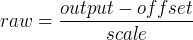 The value for scale can be obtained analytically by doing a unit analysis, i.e., units are [output SI units]/[actuator units]. For example, on a machine with a velocity mode amplifier such that 1 volt results in 250 mm/sec velocity,
  Note that the units of the offset are in machine units, e.g., mm/sec, and they are pre-subtracted from the sensor readings. The value for this offset is obtained by finding the value of your output which yields 0.0 for the actuator output. If the DAC is linearized, this offset is normally 0.0.
The scale and offset can be used to linearize the DAC as well, resulting in values that reflect the combined effects of amplifier gain, DAC non-linearity, DAC units, etc. To do this, follow this procedure:
- Build a calibration table for the output, driving the DAC with a desired voltage and measuring the result. See table [.] for an example of voltage measurements.
- Do a least-squares linear fit to get coefficients a, b such thatmeas=a*raw+b
- Note that we want raw output such that our measured result is identical to the commanded output. This means
- cmd=a*raw+b
- raw=(cmd-b)/a
- As a result, the a and b coefficients from the linear fit can be used as the scale and offset for the controller directly.
- MAX_OUTPUT
- = 10 (hal) The maximum value for the output of the PID compensation that is written to the motor amplifier, in volts. The computed output value is clamped to this limit. The limit is applied before scaling to raw output units. The value is applied symmetrically to both the plus and the minus side.
Output Voltage Measurements
|
Raw |
Measured |
|
-10 |
-9.93 |
|
-9 |
-8.83 |
|
0 |
-0.03 |
|
1 |
0.96 |
|
9 |
9.87 |
|
10 |
10.87 |
Table: - INPUT_SCALE
- = 20000 (hal) Specifies the number of pulses that corresponds to a move of one machine unit. A second number, if specified, is ignored.
For example, on a 2000 counts per rev encoder, and 10 revs/inch gearing, and desired units of inch, we have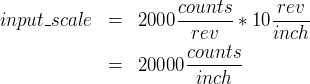
The following items are Stepper related items.
- SCALE
- = 4000 (hal) Specifies the number of pulses that corresponds to a move of one machine unit. For stepper systems, this is the number of step pulses issued per machine unit. For servo systems, this is the number of feedback pulses per machine unit. A second number, if specified, is ignored.
For example, on a 1.8 degree stepper motor with half-stepping, and 10 revs/inch gearing, and desired units of inch, we have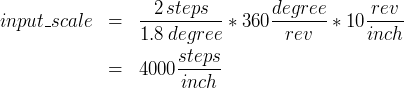 Older stepper configuration .ini and .hal used INPUT_SCALE for this value.
 - STEPGEN_MAXACCEL
- = 21.0 (hal) Acceleration limit for the step generator. This should be 1% to 10% larger than the axis MAX_ACCELERATION. This value improves the tuning of stepgen's "position loop". If you have added backlash compensation to an axis then this should be 1.5 to 2 times greater than MAX_ACCELERATION.
- STEPGEN_MAXVEL
- = 1.4 (hal) Older configuration files have a velocity limit for the step generator as well. If specified, it should also be 1% to 10% larger than the axis MAX_VELOCITY. Subsequent testing has shown that use of STEPGEN_MAXVEL does not improve the tuning of stepgen's position loop.
2.2.10 [EMCIO] Section
- CYCLE_TIME
- = 0.100 The period, in seconds, at which EMCIO will run. Making it 0.0 or a negative number will tell EMCIO not to sleep at all. There is usually no need to change this number.
- TOOL_TABLE
- = tool.tbl The file which contains tool information, described in the User Manual.
- TOOL_CHANGE_POSITION
- = 0 0 2 Specifies the X Y Z location to move to when performing a tool change if three digits are used. Specifies the X Y Z A B C location when 6 digits are used. Specifies the X Y Z A B C U V W location when 9 digits are used. Tool Changes can be combined. For example if you combine the quill up with change position you can move the Z first then the X and Y.
- TOOL_CHANGE_WITH_SPINDLE_ON = 1
- The spindle will be left on during the tool change when the value is 1. Useful for lathes mostly.
- TOOL_CHANGE_QUILL_UP = 1
- The Z axis will be moved to machine zero prior to the tool change when the value is 1. This is the same as issuing a G0 G53 Z0.
- TOOL_CHANGE_AT_G30 = 1
- The machine is moved to reference point defined by parameters 5181-5186 for G30 if the value is 1. For more information on G30 and Parameters see the G Code Manual.
Index
Footnotes
1
Don't confuse a text editor with a word processor. A text editor like gedit or kwrite produce files that are plain text. They also produce lines of text that are separated from each other. A word processor like Open Office produce files with paragraphs and word wrapping and lots of embedded codes that control font size and such. A text editor does none of this. back
2
Usually this file is in the users home directory (e.g. /home/user/ ) back