AXIS is a graphical front-end for emc2 which features a live preview and backplot. It is written in Python and uses Tk and OpenGL to display its user interface.
To select AXIS as the front-end for emc2, edit the .ini file. In the section [DISPLAY] change the DISPLAY line to read
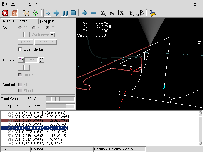
When you start AXIS, a window like the one in Figure ![[*]](crossref.png) is shown.
is shown.
The AXIS window contains the following elements:
From left to right, the toolbar buttons are:
In the upper-left corner of the program display is the coordinate
display. It shows the position of the machine. To the left of the
axis name, an origin symbol ( )
is shown if the axis has been properly homed. To the right of the
axis name, a limit symbol (
)
is shown if the axis has been properly homed. To the right of the
axis name, a limit symbol ( ) is shown
if the axis is on one of its limit switches.
) is shown
if the axis is on one of its limit switches.
To properly interpret these numbers, refer to the ``Position:''
indicator in the status bar. If the position is ``Absolute'',
then the displayed number is in the machine coordinate system. If
it is ``Relative'', then the displayed number is in the offset
coordinate system. When the coordinates displayed are relative, the
display will include a cyan ``machine origin'' marker ( ).
If the position is ``Commanded'', then it is the ideal position-for
instance, the exact coordinate given in a G0 command. If
it is ``Actual'', then it is the position the machine has actually
been moved to. These values can differ for several reasons: Following
error, deadband, encoder resolution, or step size. For instance, if
you command a movement to X 0.0033 on your mill, but one step of your
stepper motor is 0.00125, then the ``Commanded'' position will
be 0.0033 but the ``Actual'' position will be 0.0025 (2 steps)
or 0.00375 (3 steps).
).
If the position is ``Commanded'', then it is the ideal position-for
instance, the exact coordinate given in a G0 command. If
it is ``Actual'', then it is the position the machine has actually
been moved to. These values can differ for several reasons: Following
error, deadband, encoder resolution, or step size. For instance, if
you command a movement to X 0.0033 on your mill, but one step of your
stepper motor is 0.00125, then the ``Commanded'' position will
be 0.0033 but the ``Actual'' position will be 0.0025 (2 steps)
or 0.00375 (3 steps).
When a file is loaded, a preview of it is shown in the display area. Fast moves (such as those produced by the G0 command) are shown as dotted green lines. Moves at a feed rate (such as those produced by the G1 command) are shown as solid white lines. Dwells (such as those produced by the G4 command) are shown as small ``X'' marks.
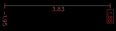
The ``extents'' of the program in each axis are shown. At each
end, the least or greatest coordinate value is indicated. In the middle,
the difference between the coordinates is shown. In Figure ,
the X extent of the file is from -2.05 to 2.09 inches, a total of
4.13 inches.
When some coordinates exceed the ``soft limits'' in the .ini file, the relevant dimension is shown in a different color. Here, the maximum limit is exceeded on the X axis:
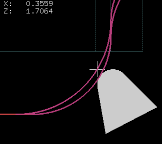
The location of the tip of the tool is indicated by the ``tool cone''. The cone does not indicate anything about the shape, length, or radius of the tool.
When a tool is loaded (for instance, with the MDI command T1M6), the cone changes to a cylinder which shows the diameter of the tool given in the tool table file.
When the machine moves, it leaves a trail called the backplot. The color of the line indicates the type of motion: Yellow for jogs, faint green for rapid movements, red for straight moves at a feed rate, and magenta for circular moves at a feed rate.
By left-clicking on a portion of the preview plot, the line will be highlighted in both the graphical and text displays. By left-clicking on an empty area, the highlighting will be removed.
By dragging with the left mouse button pressed, the preview plot will be shifted (panned).
By dragging with shift and the left mouse button pressed, or by dragging with the mouse wheel pressed, the preview plot will be rotated. When a line is highlighted, the center of rotation is the center of the line. Otherwise, the center of rotation is the center of the file as a whole.
By rotating the mouse wheel, or by dragging with the right mouse button pressed, or by dragging with control and the left mouse button pressed, the preview plot will be zoomed in or out.
By clicking one of the ``Preset View'' icons, or by pressing ``V'', several preset views may be selected.
By left-clicking a line of the program, the line will be highlighted in both the graphical and text displays.
When the program is running, the line currently being executed is highlighted in red. If no line has been selected by the user, the text display will automatically scroll to show the current line.
While the machine is turned on but not running a program, the items in the ``Manual Control'' tab can be used to move the machining center or turn different parts of it on and off.
When the machine is not turned on, or when a program is running, the manual controls are unavailable.
Many of the items described below are not useful on all machines. When AXIS detects that a particular pin is not connected in HAL, the corresponding item in the Manual Control tab is removed. For instance, if the HAL pin motion.spindle-brake is not connected, then the ``Brake'' button will not appear on the screen. If the environment variable AXIS_NO_AUTOCONFIGURE is set, this behavior is disabled and all the items will appear.
``Axis'' allows you to manually move the machine. This action is known as ``jogging''. First, select the axis to be moved by clicking it. Then, click and hold the ``+'' or ``-'' button depending on the desired direction of motion. The first four axes can also be moved by the arrow keys (X and Y), PAGE UP and PAGE DOWN keys (Z) and the [ and ] keys (A).
If ``Continuous'' is selected, the motion will continue as long as the button or key is pressed. If another value is selected, the machine will move exactly the displayed distance each time the button is clicked or the key is pressed. By default, the available values are:
0.1000 0.0100 0.0010 0.0001The .ini file setting [DISPLAY]INCREMENTS can be used to override the default. Its value can contain decimal numbers (e.g., 0.1000) or fractional numbers (e.g., 1/16). For machines configured as metric, a good setting might be
for more information on
homing.
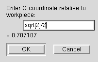
By pressing ``Touch Off'' or the END key, the ``G54 offset'' for the current axis is changed so that the current axis value will be the specified value. Expressions may be entered using the rules for rs274ngc programs, except that variables may not be referred to. The resulting value is shown as a number.
By pressing ``Override Limits'', the machine will temporarily be permitted to jog outside the limits defined in the .ini file.
The buttons on the first row select the direction for the spindle to rotate: Counterclockwise, Stopped, Clockwise. The buttons on the next row increase or decrease the rotation speed. The checkbox on the third row allows the spindle brake to be engaged or released. Depending on your machine configuration, not all the items in this group may appear.
The two buttons allow the ``Mist'' and ``Flood'' coolants to be turned on and off. Depending on your machine configuration, not all the items in this group may appear.
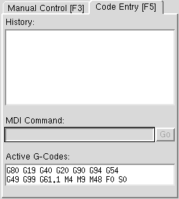
Code Entry'' (also called MDI), allows G-code programs can be entered manually, one line at a time. When the machine is not turned on, or when a program is running, the code entry controls are unavailable.
This shows MDI commands that have been typed earlier in this session.
This allows you to enter a g-code command to be executed. Execute the command by pressing Enter or by clicking ``Go''.
This shows the ``modal codes'' that are active in the interpreter. For instance, ``G54'' indicates that the ``G54 offset'' is applied to all coordinates that are entered.
By moving this slider, the programmed feed rate can be modified. For instance, if a program requests F60 and the slider is set to 120%, then the resulting feed rate will be 72.
By moving this slider, the programmed spindle feed rate can be modified. For instance, if a program requests F8000 and the slider is set to 80%, then the resulting spindle speed will be 6400. This item only appears when the HAL pin motion.spindle-speed-out is connected.
By moving this slider, the speed of jogs can be modified. For instance, if the slider is set to 1 in/min, then a .01 inch jog will complete in about .6 seconds, or 1/100 of a minute. Near the left side (slow jogs) the values are spaced closely together, while near the right side (fast jogs) they are spaced much further apart, allowing a wide range of jog speeds with fine control when it is most important.
On machines with a rotary axis, a second jog speed slider is shown. This slider sets the jog rate for the rotary axes (A, B and C).
Almost all actions in AXIS can be accomplished with the keyboard. A full list of keyboard shortcuts can be found in the AXIS Quick Reference, which can be displayed by choosing HELP > QUICK REFERENCE. Many of the shortcuts are unavailable when in Code Entry mode.
The most frequently used keyboard shortcuts are shown in Table .
|
|
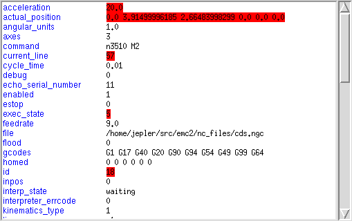
AXIS includes a program called ``emctop'' which shows some of the details of emc's state. You can run this program by invoking MACHINE > SHOW EMC STATUS
The name of each item is shown in the left column. The current value is shown in the right column. If the value has recently changed, it is shown on a red background.
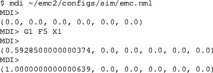
AXIS includes a program called ``mdi'' which allows text-mode entry of MDI commands to a running emc session. You can run this program by opening a terminal and typing
.
AXIS includes a program called ``axis-remote'' which can send certain commands to a running AXIS. The available commands are shown by running axis-remote -help and include checking whether AXIS is running (-ping), loading a file by name, reloading the currently loaded file (-reload), and making AXIS exit (-quit).
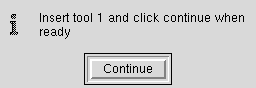
AXIS includes a userspace hal component called ``hal_manualtoolchange'',
which shows a window (Figure ) when
a M6 command is issued. After the OK button is pressed, execution
of the program will continue.
The HAL configuration file configs/sim/axis_manualtoolchange.hal shows the HAL commands necessary to use this component.
hal_manualtoolchange can be used even when AXIS is not used as the GUI.
AXIS includes several Python modules which may be useful to others. For more information on one of these modules, use ``pydoc <module name>'' or read the source code. These modules include:
By including the line
Pressing ``V'' zooms out to show the entire file, if one is loaded.
When in lathe mode, the shape of the loaded tool (if any) is shown.
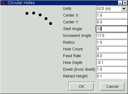
AXIS has the ability to send loaded files through a ``filter program''. This filter can do any desired task: Something as simple as making sure the file ends with 'M2', or something as complicated as detecting whether the input is a depth image, and generating g-code to mill the shape it defines.
The [FILTER] section of the ini file controls how filters work. First, for each type of file, write a PROGRAM_EXTENSION line. Then, specify the program to execute for each type of file. This program is given the name of the input file as its first argument, and must write rs274ngc code to standard output. This output is what will be displayed in the text area, previewed in the display area, and executed by emc when ``Run''.
The colors of most elements of the AXIS user interface can be customized through the X Resource Database. The sample file axis_light_background changes the colors of the backplot window to a ``dark lines on white background'' scheme, and also serves as a reference for the configurable items in the display area.
For information about the other items which can be configured in Tk applications, see the Tk manpages.
Because modern desktop environments automatically make some settings in the X Resource Database that adversely affect AXIS, by default these settings are ignored. To make the X Resource Database items override AXIS defaults, include the following line in your X Resources:
To improve the interaction of AXIS with physical jog wheels, the axis currently selected in the GUI is also reported on a pin with a name like axisui.jog.x. Except for a short time when the active axis has just been changed, exactly one of these pins is TRUE at one time, and the rest are FALSE.
After AXIS has created these HAL pins, it executes the halfile named in [HAL]POSTGUI_HALFILE. Unlike [HAL]HALFILE, only one such file may be used.
If it exists, the contents of ~/.axisrc are executed as Python source code just before the AXIS gui is displayed. The details of what may be written in the axisrc are subject to change during the development cycle.
The lines shown in Figure add Control-Q
as a keyboard shortcut for Quit.